
Audio visual system and decoder therefor

a decoder and audio visual technology, applied in the field of audio visual system and decoder therefor, can solve the problems of s/pdif output having a delay relative to hd output, reducing the processing burden of delay control of the synchronization process, and not performing the addition process of the engin

Inactive Publication Date: 2014-11-25
SONY CORP
View PDF11 Cites 4 Cited by
  • Summary
  • Abstract
  • Description
  • Claims
  • Application Information

AI Technical Summary

Benefits of technology

The patent is about an audio visual system and decoder that can reduce processing burdens when there are multiple output paths that require a synchronization process. By using a delay control for the synchronization process, the system can reduce processing burdens caused by the delay control. Overall, the patent aims to improve the efficiency and performance of the audio visual system.

Problems solved by technology

However, for the SD output, the above additional process is not performed by the engine even for video signals from the same source.
In this case, the HD output may have a delay relative to the SD output due to the process by the engine.
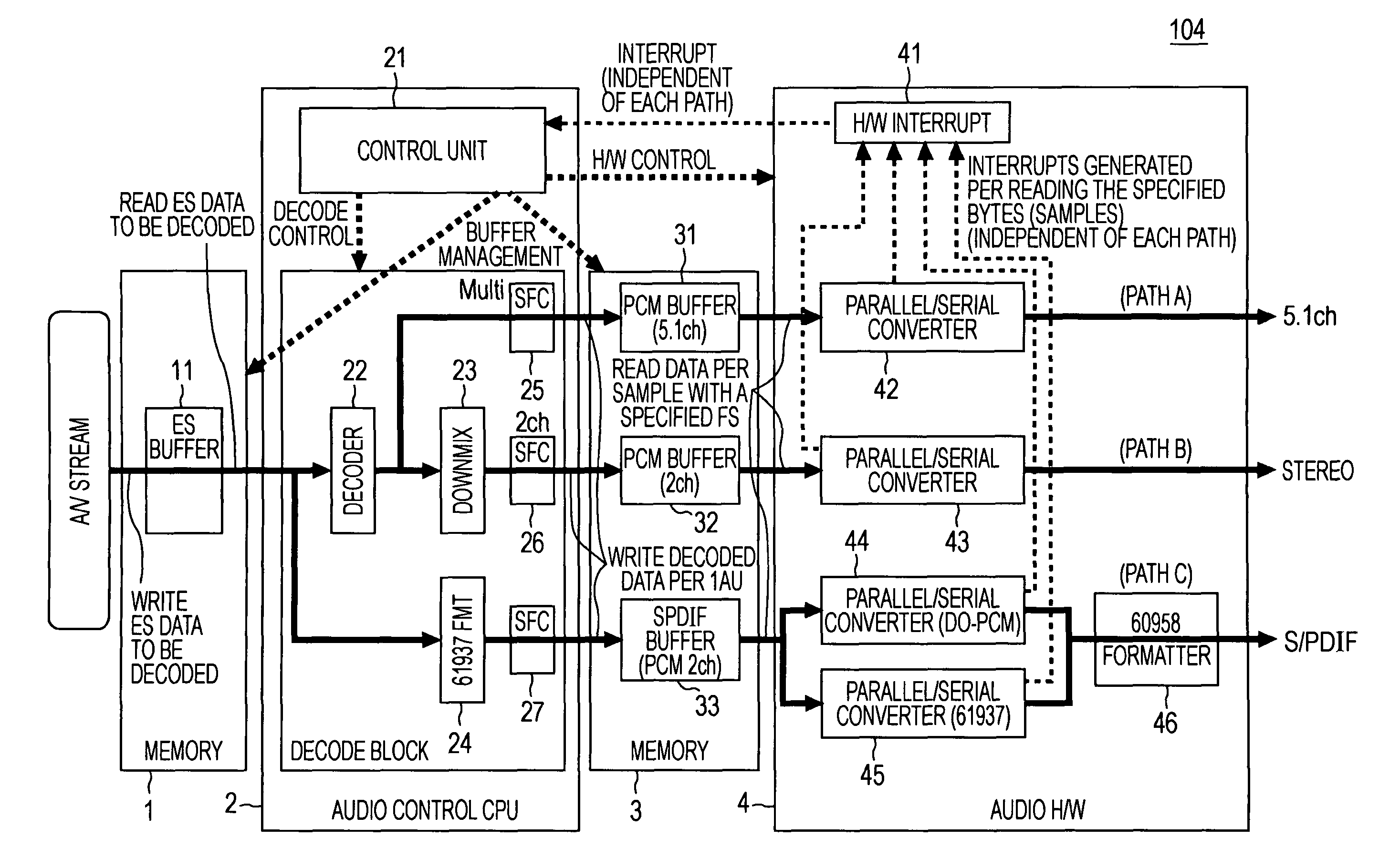
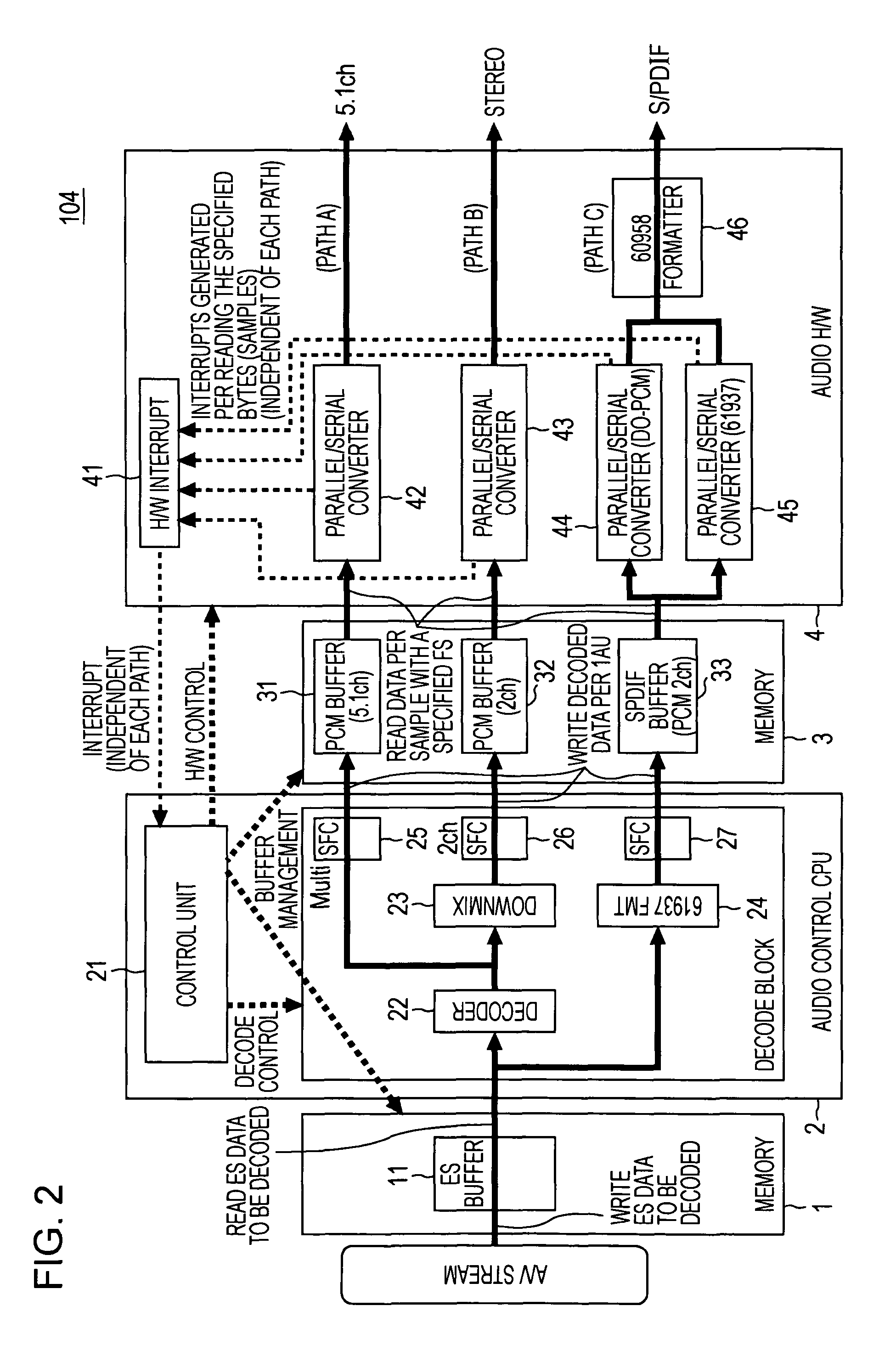
Additionally, in a case of audio signals for example, the S / PDIF output may have a delay relative to the multi-channel output or the stereo output due to the decode process.

Method used


Image

  • Audio visual system and decoder therefor
  • Audio visual system and decoder therefor
  • Audio visual system and decoder therefor

Examples


Embodiment Construction

[0023]Now an embodiment of the present invention will be described.

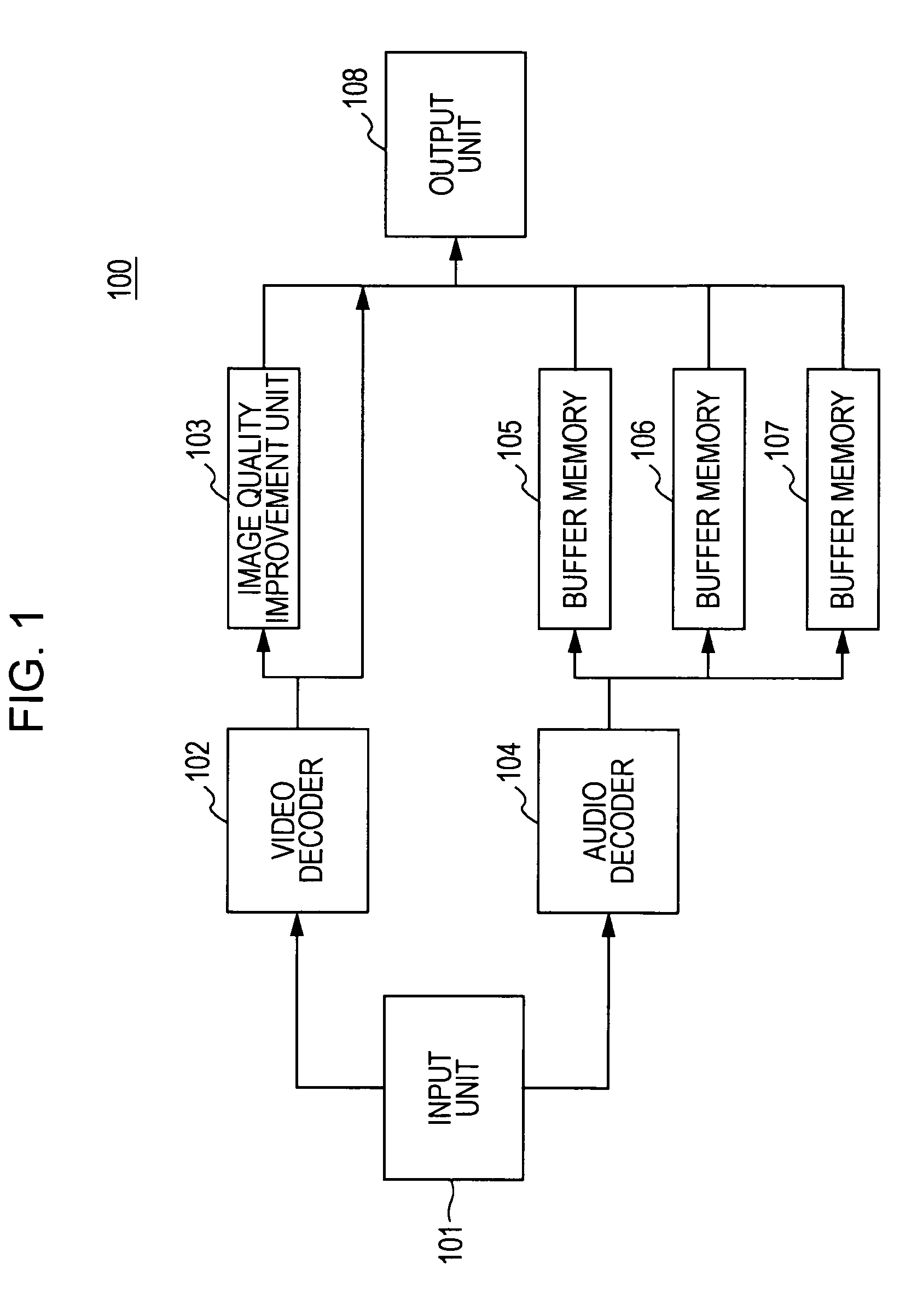
[0024]FIG. 1 illustrates a block diagram of an exemplary configuration of Audio-Visual (AV) system 100 according to an embodiment of the present invention.

[0025]As shown in FIG. 1, AV system 100 includes an input unit 101, a video decoder 102, an image quality improvement unit 103, an audio decoder 104, buffer memories 105 to 107, and an output unit 108.

[0026]The input unit 101 receives data input. The data input into the input unit 101 is streaming data in which video data and audio data are superimposed. The AV streaming data to be received by the input unit 101 is streaming data in the MPEG2 format, for example.

[0027]The input unit 101 then divides the AV data input in the input unit 101 into video data and audio data, which in turn are transferred to the video decoder 102 and the audio decoder 104, respectively.

[0028]The video decoder 102 decodes the video streaming data transferred from the input unit 101. The v...


PUM


Abstract

An audio visual system includes an input unit for receiving data containing video data and audio data and dividing the data into the audio data and the video data, a video decoder for decoding the video data divided by the input unit, an audio decoder for decoding the audio data divided by the input unit, and an output unit for superimposing and outputting the video data decoded by the video decoder and the audio data decoded by the audio decoder. The video decoder or audio decoder has a plurality of data output paths and sets delay times for each of the output paths to synchronize the decoded video data with the decoded audio data.

Description

BACKGROUND OF THE INVENTION[0001]1. Field of the Invention[0002]The present invention relates to an audio visual system and a decoder therefor for decoding audio data and video data and outputting them in a synchronized manner in response to an input of AV data with those data superimposed therein.[0003]2. Description of the Related Art[0004]Recently, a variety of video and audio equipments have been prevailed. A user can obtain video and audio signals in various output forms from the same source data by selecting an output path that satisfies his / her intention. For instance, output paths of video signals include a high definition (HD) output and a standard definition (SD) output. The HD output is defined as a high-definition or high-resolution video output, while the SD output is defined as an image output having standard resolution or image quality. Meanwhile, output paths for audio signals include a multi-channel (e.g., 5.1 channel) output, a stereo (2 channel) output, the Sony / P...

Claims


Application Information

Patent Timeline
Patent Type & Authority Patents(United States)
IPC IPC(8): H04N19/00H04N21/43H04N7/12H04N19/61H04N21/2368H04N5/44H04N5/937H04N21/434H04N5/93
CPCH04N19/61H04N19/103H04N7/26335H04N21/2368H04N19/44H04N21/4341H04N21/4307H04N7/52H04N7/50H04N21/43072
Inventor YOSHIMURA, MASAKIYAMAUCHI, KOJI
Owner SONY CORP
Learn More