
Open-end spinning rotor

a technology of open-end spinning and rotor, which is applied in the direction of open-end spinning machines, continuous wounding machines, and paper-making machines, etc., can solve the problems of large imprecision, long connecting pins are rather unfavorable for handling, and purely non-positive torque transmission no longer works reliably

Active Publication Date: 2014-11-04
SAURER SPINNING SOLUTIONS GMBH & CO KG
View PDF33 Cites 2 Cited by
  • Summary
  • Abstract
  • Description
  • Claims
  • Application Information

AI Technical Summary

Benefits of technology

[0011]The object of the present invention is to provide, proceeding from German Patent Document DE 196 18 027 A1, a spinning rotor with a compact and reliable coupling device.
[0013]The invention easily realises a positive connection to transmit a torque from the rotor shaft to the rotor cup. Consequently, the torque can also be reliably transmitted at relatively high rotational speeds. Owing to the shape according to the invention of the holding element for the locking bodies, a compact and space-saving arrangement is provided. A separate axle element for the positive connection is not required. The arrangement according to the invention has few individual parts. As a result, an adding up of manufacturing tolerances can be reduced, so the spinning rotor has a small imbalance.
[0019]The stops have stop faces. The stop faces are preferably arranged perpendicular to the axis of the open-end spinning rotor and their geometric focal point is located on the axis of the open-end spinning rotor. In this configuration of the stops, a centring of the rotor cup is additionally achieved by the axial force against the stops. In other words, an angular offset between the axis of the rotor shaft and the axis of the rotor cup is avoided.
[0020]Spherical locking bodies are particularly advantageous for centrifugal force couplings of the claimed type. A spherical locking body works particularly effectively in conjunction with a V-shaped groove on the hub. The spherical locking body rests on an oblique face of the groove, so that the centrifugal force is converted into an axial force.

Problems solved by technology

The long connecting pins are rather unfavourable for handling.
The disadvantage in this arrangement is that with an increasing rotational speed of the spinning rotor, the purely non-positive transmission of the torque no longer works reliably.
The manufacturing tolerances add up in accordance with the number of components, so that more components lead to greater imprecisions and therefore to a greater imbalance.
At the high rotational speeds at which spinning rotors are operated, this imbalance can lead to problems, through to damage to the spinning unit.

Method used


Image

  • Open-end spinning rotor
  • Open-end spinning rotor
  • Open-end spinning rotor

Examples


Embodiment Construction

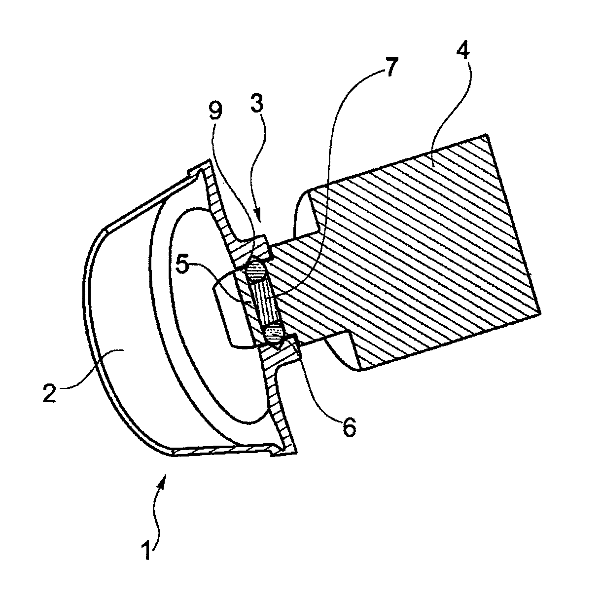
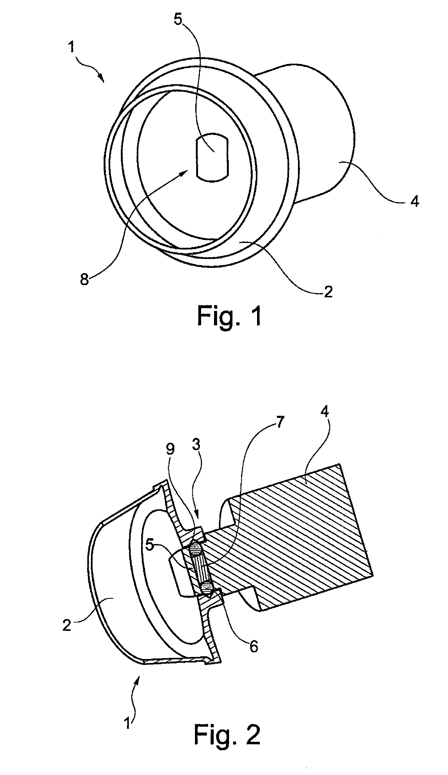
[0031]FIGS. 1 and 2 show a spinning rotor 1 according to the invention. The spinning rotor 1 comprises a rotor shaft 4 and a rotor cup 2. The rotor shaft 4 and the rotor cup 2 are releaseably connected to one another, so the rotor cup 2 can be exchanged when necessary. The rotor shaft 4 is connected to a drive, not shown. As the rotor cup 2 is exchangeable, the rotor shaft 4 can be rigidly integrated in the drive, preferably a single drive.

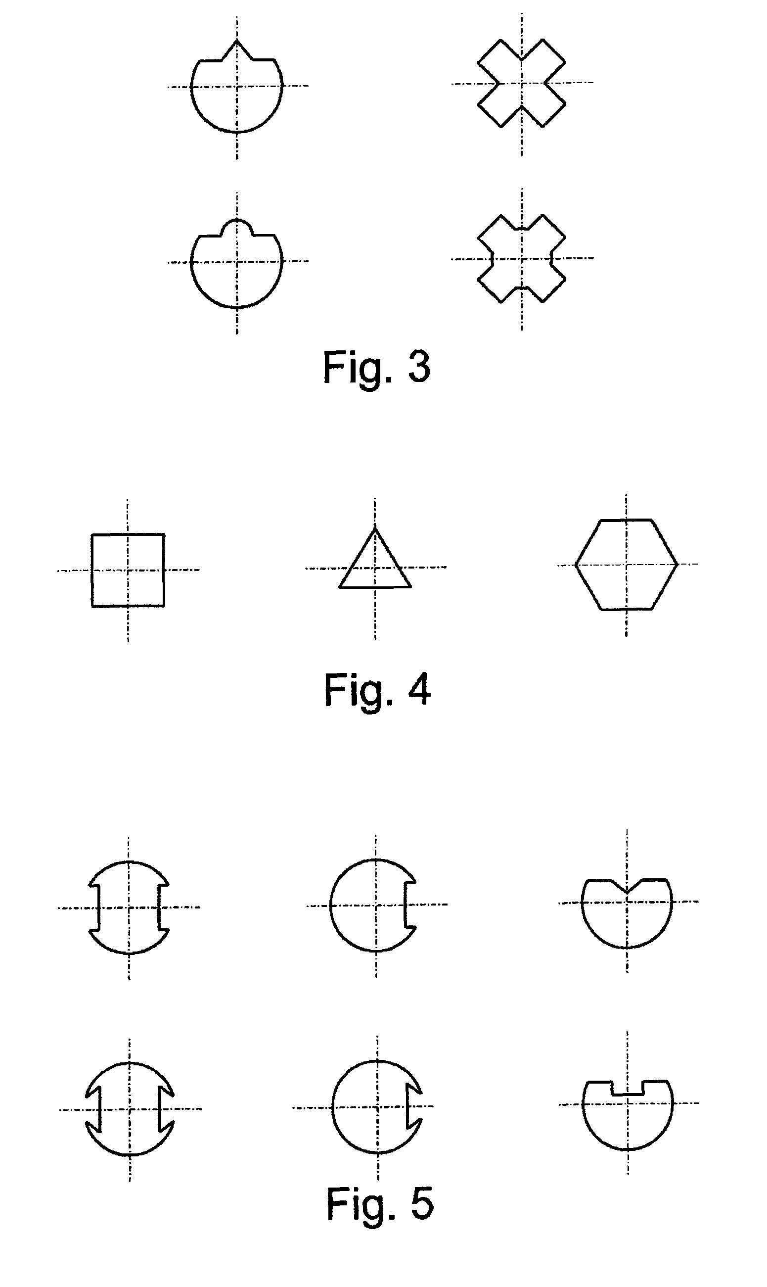
[0032]In order to realise a releasable connection, the spinning rotor 1 has a coupling device 3. In the embodiment shown, the rotor shaft 4 comprises a pin 5 and the rotor cup 2 a hub 8. The external shape of the pin 5 and the internal shape of the hub 8 correspond to one another, so when placing the rotor cup 2 on the pin 5 of the rotor shaft 4, a positive shaft-hub connection is produced and therefore a torque can be transmitted. The embodiment shown in FIGS. 1 and 2 has a pin 5 with a circular cylindrical external shape. In order to achieve a p...


PUM

PropertyMeasurementUnit
centrifugal forceaaaaaaaaaa
forceaaaaaaaaaa
circular cylindrical shapeaaaaaaaaaa

Abstract

An open-end spinning rotor (1), comprising a rotor shaft (4), a rotor cup (2) and a coupling device (3) releasably connecting the rotor shaft (4) and rotor cup (2). The coupling device (3) has locking bodies (6), arranged in a holding element (5) and lock the rotor cup (2) and the rotor shaft (4) in the axial direction under centrifugal force during operation of the open-end spinning rotor (1). A resilient element (7) is associated with the locking bodies (6) and cooperates with the locking bodies (6) such that the locking bodies (6) also lock the rotor cup (2) to the rotor shaft (4) in the axial direction at a standstill. The holding element (5) is configured as a pin which is formed such that it produces a positive shaft-hub connection between the rotor shaft (4) and rotor cup (2) in conjunction with a correspondingly formed hub (8).

Description

BACKGROUND OF THE INVENTION[0001]The present invention relates to an open-end spinning rotor, comprising a rotor shaft, a rotor cup and a coupling device to releasably connect the rotor shaft and rotor cup, the coupling device having locking bodies, which are arranged in a holding element and lock the rotor cup and the rotor shaft in the axial direction as a consequence of the centrifugal force during operation of the open-end spinning rotor, and wherein a resilient element is associated with the locking bodies and the resilient element cooperates with the locking bodies in such a way that the locking bodies also lock the rotor cup to the rotor shaft in the axial direction at a standstill.[0002]In the past, open-end rotor spinning machines used in the textile industry were usually designed in such a way that the spinning rotors were mounted with their rotor shaft in the bearing interstices of a so-called support disc bearing arrangement and were driven, in this case, by means of a t...

Claims


Application Information

Patent Timeline
Patent Type & Authority Patents(United States)
IPC IPC(8): D01H4/10D01H4/12
CPCD01H4/10D01H4/12
Inventor WASSENHOVEN, HEINZ-GEORG
Owner SAURER SPINNING SOLUTIONS GMBH & CO KG
Learn More