Head band

a headband and band technology, applied in the field of head bands, can solve the problems of scattered welding materials toward the welder's face, the welder is likely to encounter several dangers,

Active Publication Date: 2014-11-04
OTOS WING
View PDF43 Cites 41 Cited by
  • Summary
  • Abstract
  • Description
  • Claims
  • Application Information

AI Technical Summary

Problems solved by technology

In the case of a welding operation, a welder is likely to encounter several dangers.
For example, a strong flash of light may temporarily blind the welder, or a welding material may be scattered toward the welder's face due to sudden heat generated during resistance welding.

Method used


Image

  • Head band
  • Head band
  • Head band

Examples


Embodiment Construction

[0031]Hereinafter, an exemplary embodiment of the present invention will be described in detail with reference to the accompanying drawings.

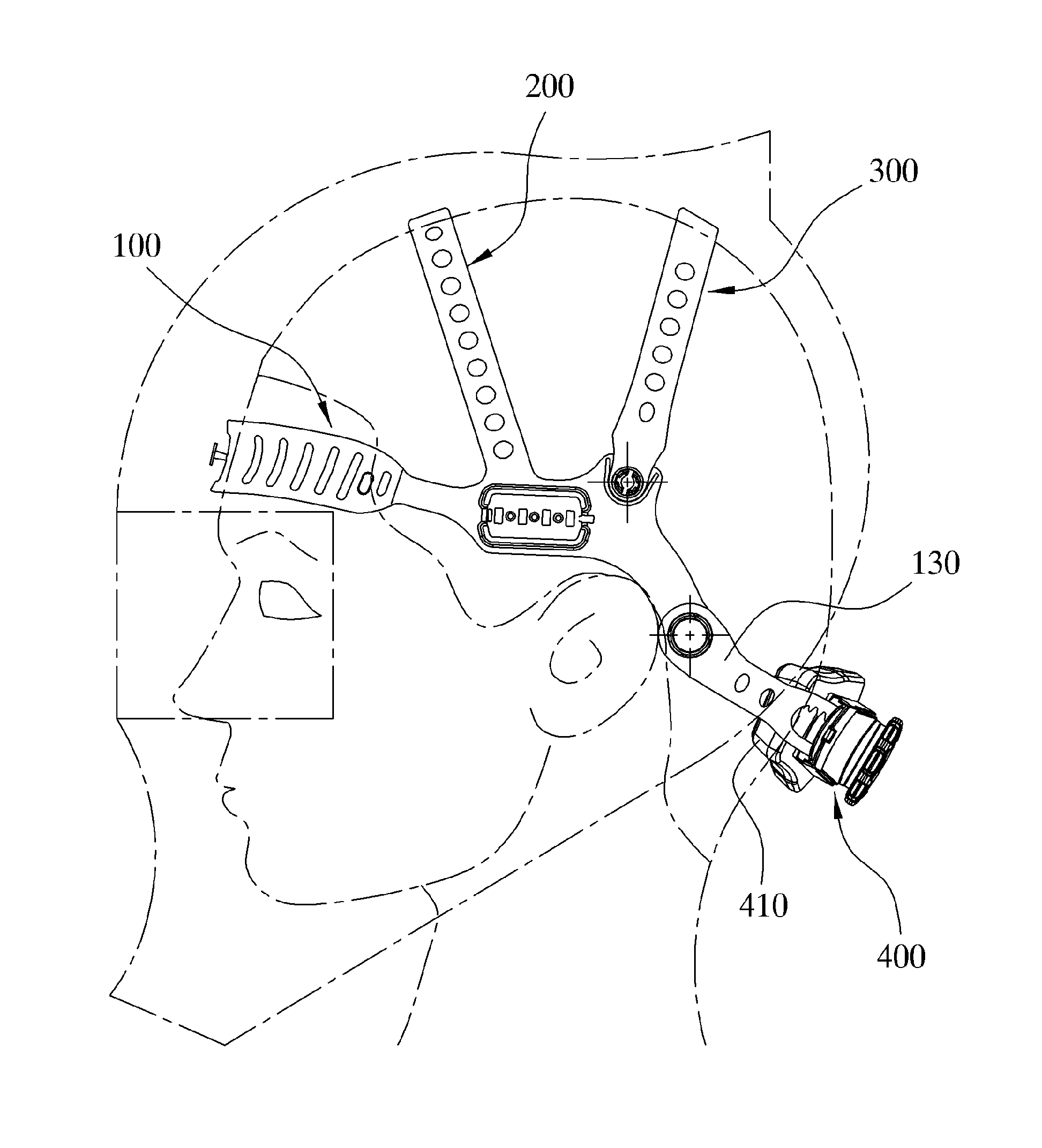
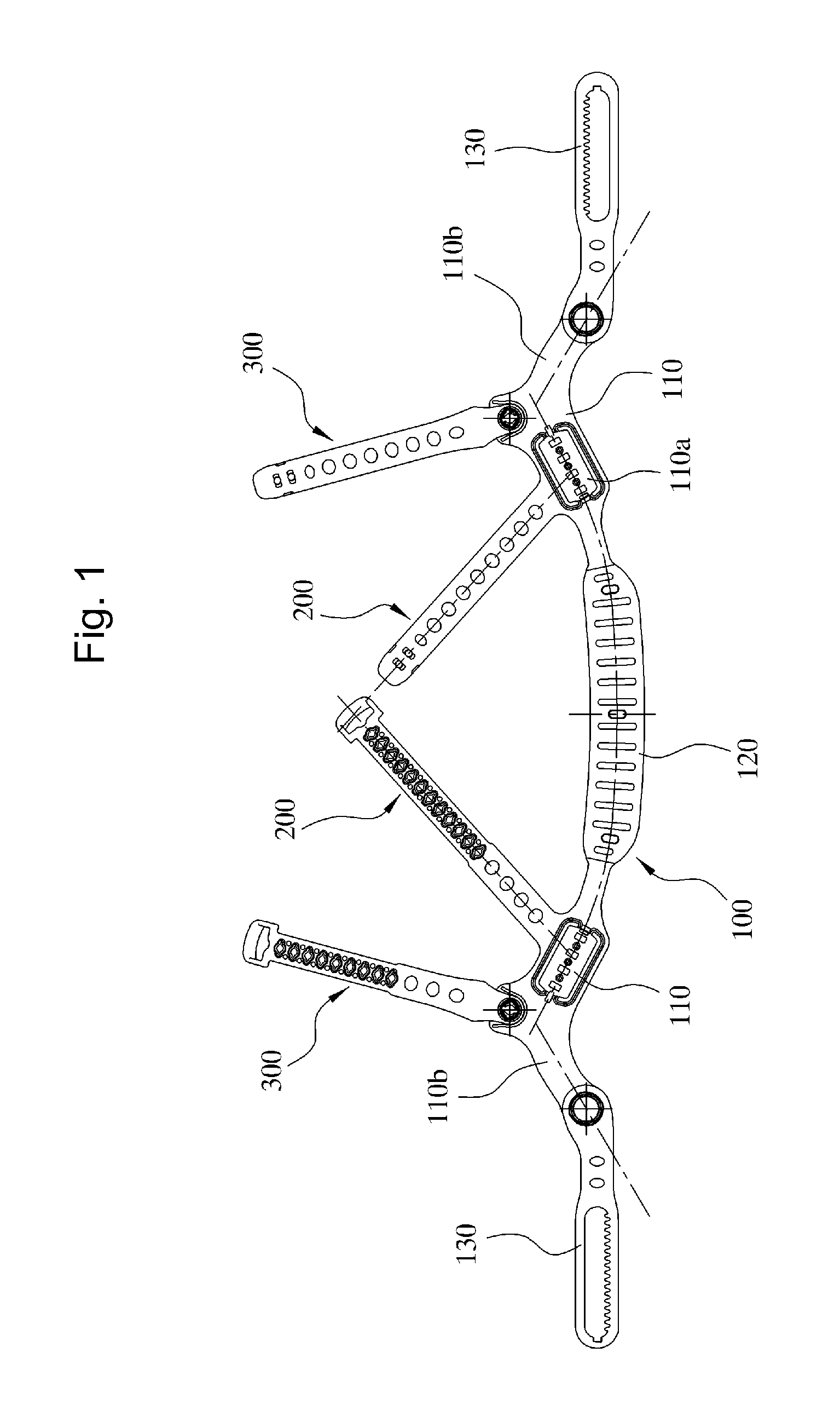
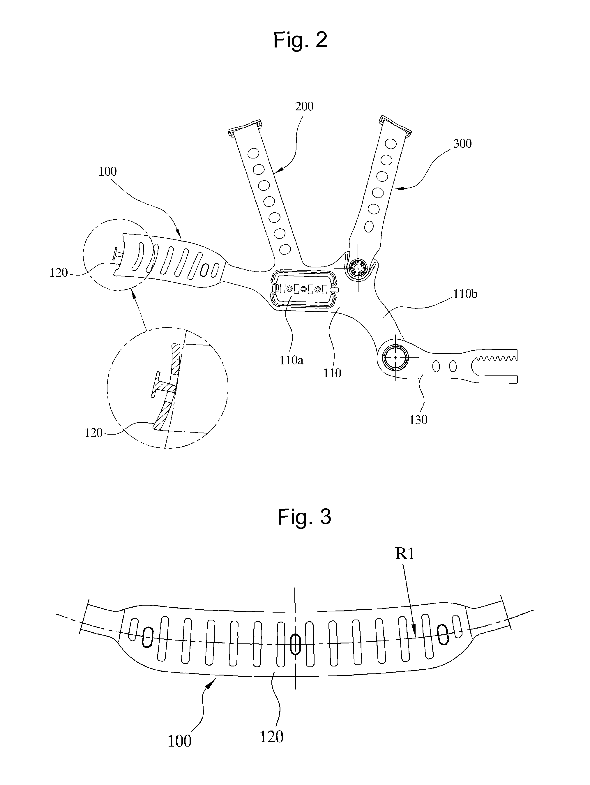
[0032]The head band of the present invention, as illustrated in FIGS. 1 to 10, includes a first band part 100 configured to surround the circumference of the head. The first band part 100 includes a pair of first sections 110 to be located at opposite lateral regions of the head, each first section 110 being provided with a coupling piece 110a for coupling with, e.g., a welding mask, a second section 120 to be located on a front region of the head, the second section 120 taking the form of an arc-shaped section having a predetermined radius of curvature when completely unrolled and being adapted to come into close contact at a predetermined gradient with the forehead, and a pair of third sections 130 to be located at a rear region of the head, the third sections 130 being connectable to each other so as to enable adjustment in the length of the ...


PUM


Abstract

Disclosed is a head band to assist a user in conveniently wearing head protective equipment on the head. The head band includes a first band part configured to surround the circumference of the head. The first band part includes first sections located at opposite lateral regions of the head and each provided with a coupling piece for coupling with the welding mask, a second section located on a front region of the head, the second section taking the form of an arc-shaped section having a predetermined radius of curvature when unrolled and being adapted to come into close contact at a predetermined gradient with the forehead, and third sections located at a rear region of the head, the third sections being connectable to each other to enable adjustment in the length of the third sections. The first band part comfortably comes into close contact with the forehead, providing wearer comfort.

Description

BACKGROUND OF THE INVENTION[0001]1. Field of the Invention[0002]The present invention relates to a head band usable with head protective equipment, such as a welding mask, a safety helmet, a face shield, etc., to assist a user in conveniently wearing the head protective equipment on the head.[0003]2. Description of the Related Art Considerable effort and research has been focused on assisting a user, i.e. a wearer, in conveniently wearing head protective equipment, such as a welding shield (welding mask), a safety helmet, a face shield, etc., without encountering any difficulty during welding.[0004]In the case of a welding operation, a welder is likely to encounter several dangers. For example, a strong flash of light may temporarily blind the welder, or a welding material may be scattered toward the welder's face due to sudden heat generated during resistance welding.[0005]A welding mask has been used as a representative example of equipment to protect the welder's eyes and face fr...

Claims


Application Information

Patent Timeline
Patent Type & Authority Patents(United States)
IPC IPC(8): A61B19/00A42B3/14A42B3/22A42B7/00
CPCA61B19/5202A42B3/225A61B2019/262A42B3/145A42B3/142A61B90/30A61B90/35A61B2090/502
Inventor HUH, MOON, YOUNG
Owner OTOS WING
Why Eureka
Try Eureka