
Asymmetric serrated edge light guide film having circular base segments

a technology of light guide film and backlight unit, which is applied in the direction of planar/plate-like light guide, lighting and heating apparatus, instruments, etc., can solve the problems of limited light diffusing capability of continuous prism or arc-shaped structures on the input surface, and achieve uniform surface illumination without sacrificing the efficiency of the backlight system

Active Publication Date: 2014-10-28
SK MICROWORKS SOLUTIONS CO LTD
View PDF13 Cites 3 Cited by
  • Summary
  • Abstract
  • Description
  • Claims
  • Application Information

AI Technical Summary

Benefits of technology

The solution provides uniform surface illumination and improved light diffusion, reducing the length of combined light regions and minimizing dark spots while maintaining light input efficiency.

Problems solved by technology

Thus the continuous prism- or arc-shaped structures on the input surface have limited light diffusing capability.

Method used


Image

  • Asymmetric serrated edge light guide film having circular base segments
  • Asymmetric serrated edge light guide film having circular base segments
  • Asymmetric serrated edge light guide film having circular base segments

Examples


examples

[0043]FIG. 10a shows a portion of the light input surface 32 of a light guide film 30 with an arc- or circular-type structure 36. The graph in FIG. 10b illustrates the light intensity for the light guide film 30 at distances 3.5 mm, 4.5 mm and 5.5 mm from the light input surface 32. FIG. 10b shows that the localized light intensity decreases as the distance increases from the light input surface, but there are still some hot spots evident at 5.5 mm. The arc- or circular-type structure solution provides some improvement for hot spots but is more effective at collimating light in line with the LED than widening the incidence angle. This is evident in the graph in FIG. 10b. In FIG. 10b, the LEDs are located at each of the vertical dotted lines and the light distribution is still not leveled out at 5.5 mm into the light guide film. It is apparent from the graph in FIG. 10b that the arc- or circular-type solution has insufficient diffusion capability.

[0044]FIG. 11a shows a portion of the...


PUM


Abstract

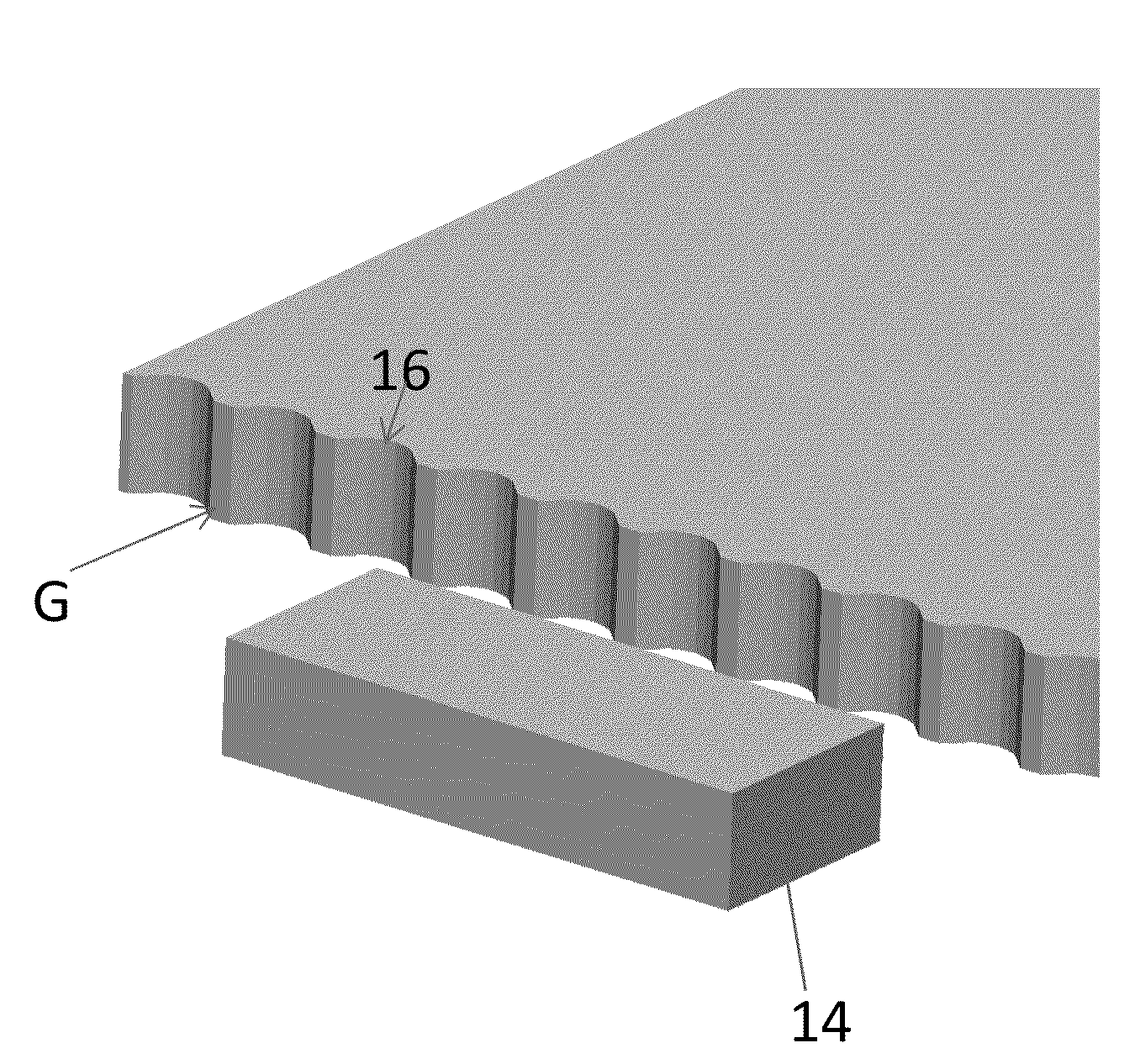
A planar light guide film for a backlight unit having at least one point light source is disclosed. The light guide film includes a light input surface for receiving light from the point light source, a light redirecting surface for redirecting light received from the light input surface and a light output surface for outputting at least the light redirected from the light redirecting surface. The light input surface further includes a composite lens structure having a first and second circular tip segment each circular tip segment with a first contact angle, and a first and second circular base segment each circular base segment with a top and bottom contact angle, the contact angles of the circular base segments being less than the contact angle of the circular tip segments.

Description

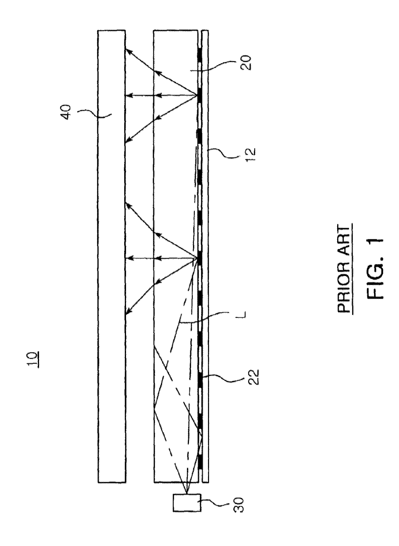
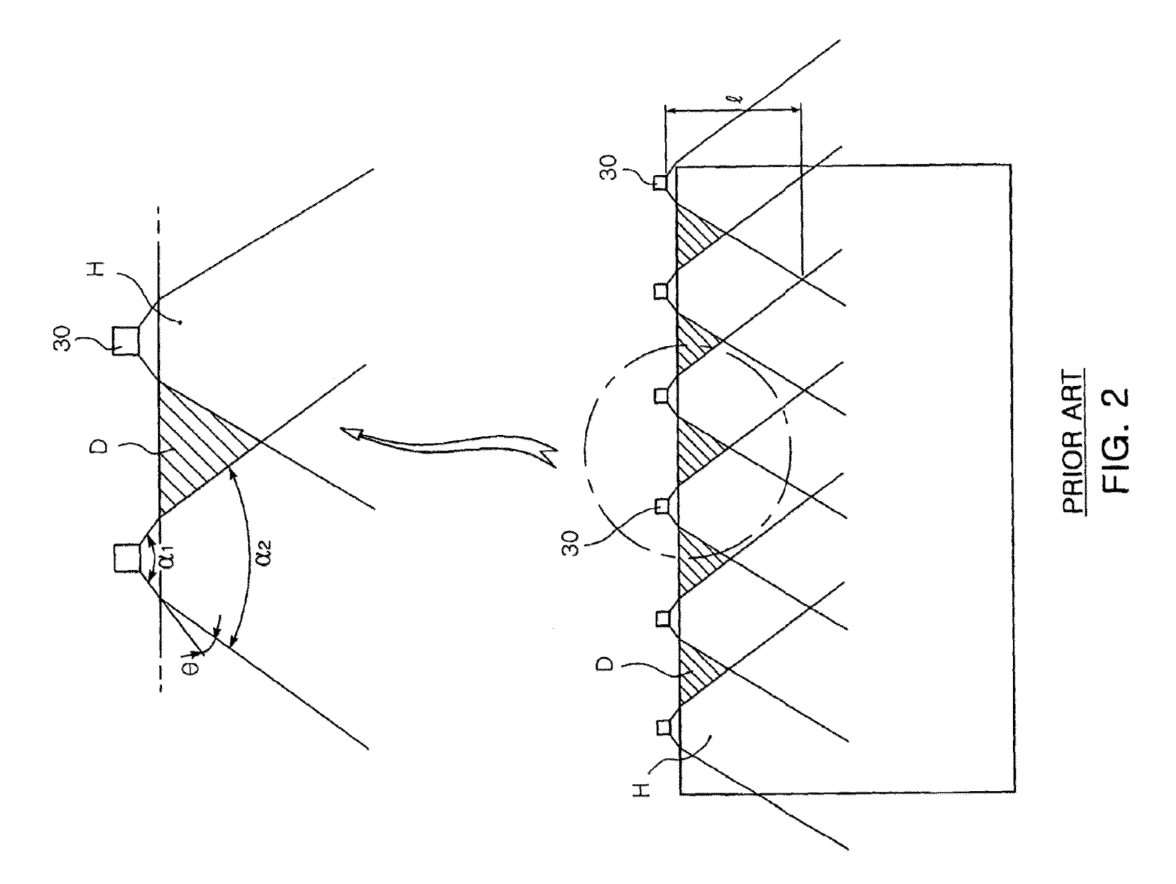
FIELD OF THE INVENTION[0001]The present invention relates to a light guide film of a light emitting diode (LED) backlight unit, and, more particularly, to a light guide film of an LED backlight unit, which has a plurality of grooves carved into an incident plane of the light guide film to increase an incidence angle of which light can be transmitted through the light guide film.BACKGROUND OF THE INVENTION[0002]Typically, a liquid crystal display (LCD) for handheld and notebook devices generally employs at least one lateral light emitting diode (LED) as a light source of a backlight unit. Such a lateral LED is generally provided to the backlight unit as shown in FIG. 1 of Yang U.S. Pat. No. 7,350,598.[0003]Referring to FIG. 1, the backlight unit 10 comprises a planar light guide film 20 disposed on a substrate 12, and a plurality of lateral LEDs 30 (only one lateral LED is shown in FIG. 1) disposed in an array on a lateral side of the light guide film 20. Light L entering the light g...

Claims


Application Information

Patent Timeline
Patent Type & Authority Patents(United States)
IPC IPC(8): F21V8/00F21V13/02F21V7/04
CPCF21V13/02G02B6/002G02B6/0016G02B6/0011
Inventor HONG, QIMALBURNE, KAREN A.
Owner SK MICROWORKS SOLUTIONS CO LTD
Learn More