Piston for a brake caliper of a disc brake

a disc brake and caliper technology, applied in the direction of mechanical equipment, machines/engines, engines without rotary main shafts, etc., can solve the problems of difficult production of pistons and relative high weight, and achieve the effect of reducing dead volume, increasing hydraulic rigidity in the brake system, and small dead volume of pistons

Active Publication Date: 2014-10-28
CONTINENTAL TEVES AG & CO OHG +1
View PDF17 Cites 6 Cited by
  • Summary
  • Abstract
  • Description
  • Claims
  • Application Information

AI Technical Summary

Benefits of technology

[0005]This object is achieved, according to aspects of the invention, by providing a recess, which is substantially at the same distance from the longitudinal axis as the projection on the inner surface of the piston head, on an outer surface of the piston head. The result of this advantageous configuration of the piston head is that the conical surface can be produced by a simple forming operation on the piston head without the need for an accumulation of material, which would increase the weight. The projection on the inner surface is therefore formed at least partially by forming the recess in the outer surface. Here, the complementary arrangement of the projection and the recess in the piston head has a positive effect on the flow of force when the disc brake is actuated mechanically. Overall, a shape-induced stiffening of the piston head is achieved with the annular recess and the projection.
[0006]A particularly advantageous configuration of the invention comprises the piston head having a substantially constant wall thickness in a certain section in the region of the conical surface. The recess and the projection on the piston head can thus be produced in a very simple manner since the flat metal sheet used as a starting material does not have to be thickened by forming operations. The conical surface on the projection on the inner surface of the piston can be produced by forming the recess in the initially still flat piston head from the outside by means of a punch, thereby causing the projection to emerge in parallel on the inner surface of the piston. To obtain a more defined conical surface on the projection, a die which has the negative shape of the projection and of the conical surface can be held against the inner surface of the piston during the forming of the recess in the outer side, as an addition to the punch.
[0007]Another possibility within the scope of the invention is for there to be a gap between the projection on the piston head and the wall of the piston. This gap can be of different sizes, the gap being more of a fold in the case of pistons with a small diameter, whereas a volume in the form of a gap is present in the case of larger piston diameters. This gap or fold is a feature of the invention which makes it possible for the first time to eliminate the need for disadvantageous thickening to form the conical surface for the mechanical actuation of a piston of a brake caliper, as was hitherto indicated in the prior art.
[0011]By connecting the cup in a sealing manner to the wall of the piston, a small dead volume of the piston is achieved since only a relatively small amount of hydraulic fluid can be accommodated in the interior of the piston. The leaktight joint between the piston and the cup can be welded by means of a laser but other forms of joining are also possible, e.g. friction welding. Reducing the dead volume in the piston and hence also in the brake caliper has the effect of increasing hydraulic rigidity in the brake system and hence of improved hydraulic behaviour.
[0012]It is central to both ways of achieving the object of the invention that the conical surface in the piston has a simple configuration which saves materials and is optimized for production. Irrespective of whether the conical surface is formed on the separate cup or on the projection in the piston head, the conical surface is advantageously configured if the conical surface encloses an angle α of 30° to 75° with the longitudinal axis of the piston in the axial direction. In this angular range, the conical surface in interaction with the drive nut of the brake caliper performs a dual function as a coupling and centring means. It is particularly advantageous if the angle α is substantially 60°.

Problems solved by technology

The conical surface is arranged at the transition between the piston head and the wall, resulting in a thickened portion in this region which leads to a relatively high weight and makes the piston difficult to produce.

Method used


Image

  • Piston for a brake caliper of a disc brake
  • Piston for a brake caliper of a disc brake
  • Piston for a brake caliper of a disc brake

Examples


Embodiment Construction

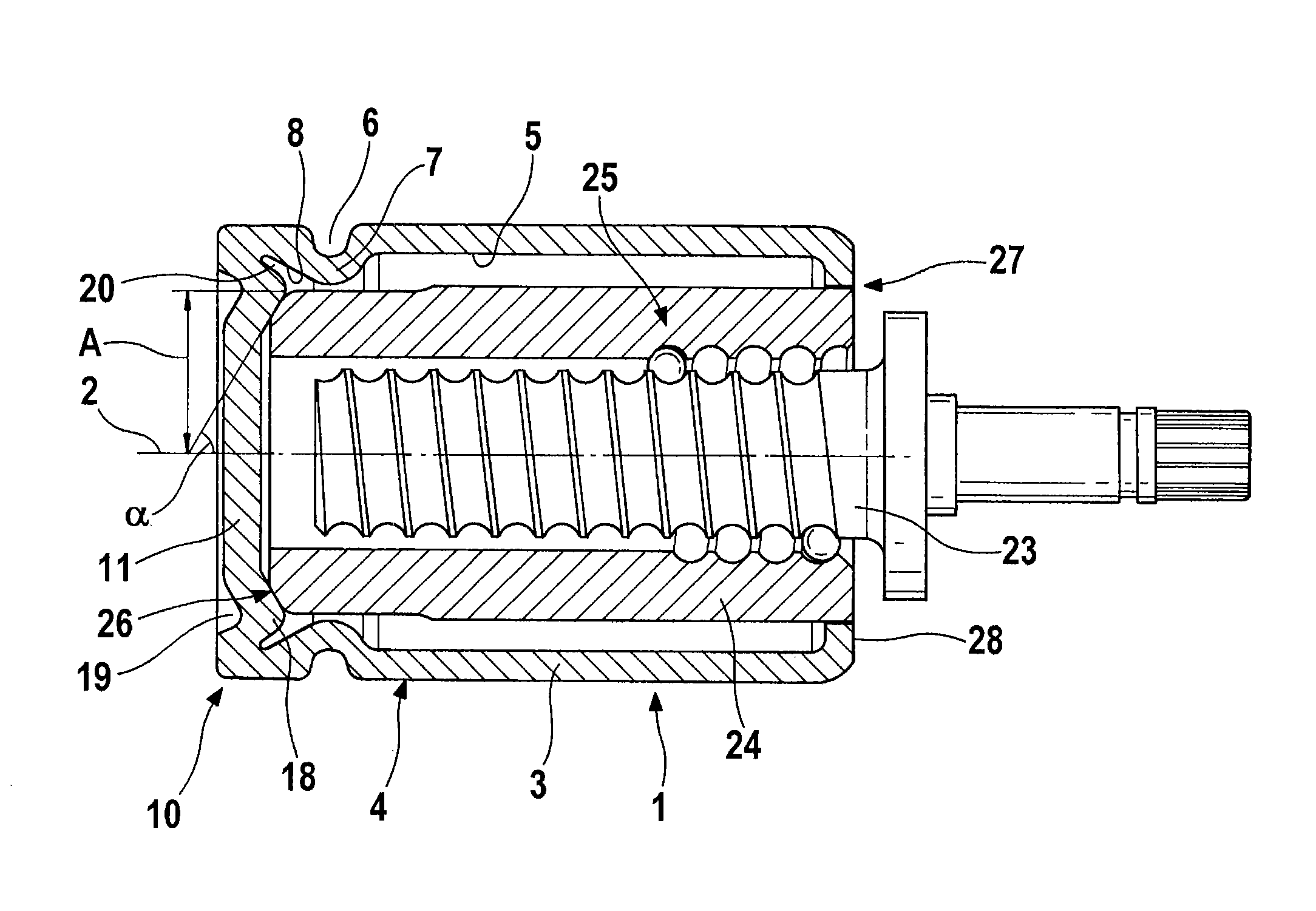
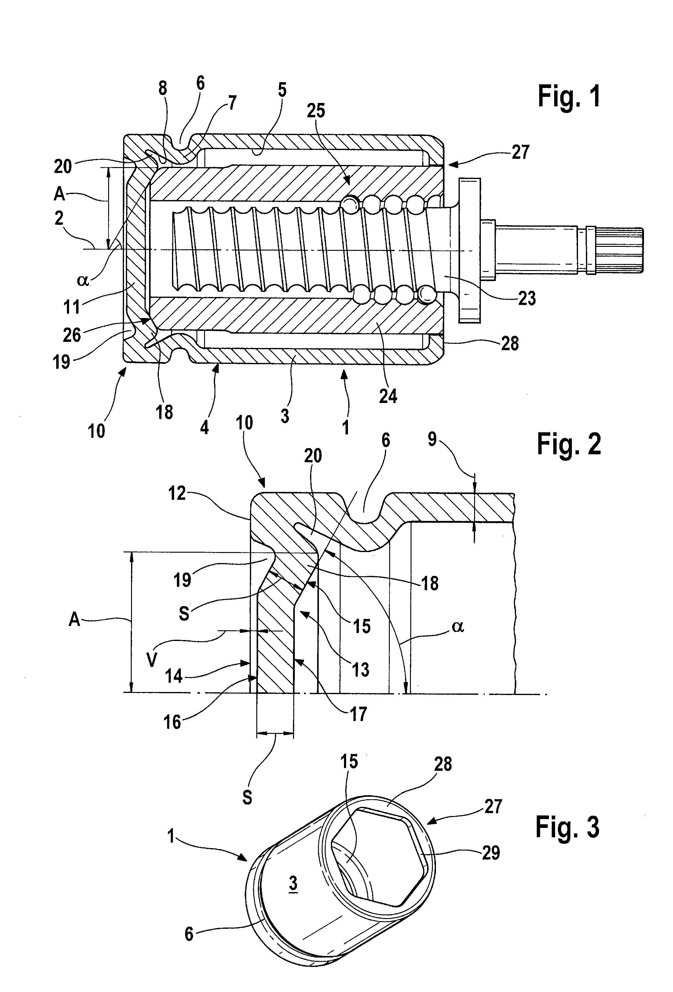
[0022]FIG. 1 shows a piston 1 with a drive spindle 23 and a drive nut 24 in longitudinal section. The piston 1, which is embodied in such a way as to be rotationally symmetrical about a longitudinal axis 2, is configured as a pot which is open at one end, having a wall 3 and a piston head 11, it being possible for the piston head 11 to be placed against a brake pad (not shown) at the closed end of the piston 1 by means of an axial contact surface 12. The contact surface 12 is larger than a cross-sectional area 9 at the weakest point of the wall 3. Moreover, a circumferential groove 6 is rolled into an outer side 4 of the wall 3 in the vicinity of the contact surface 12, the said groove serving to receive a piston protection cap (not shown) when the piston is installed in the brake caliper. The contour of the rolled-in groove 6 is continued throughout the entire cross section of the wall 3 and thus gives rise to a shoulder 7 on an inner side 5 of the wall 3 of the piston 1.

[0023]Arra...


PUM


Abstract

A piston for a brake caliper of a disc brake constructed as a pot which is open at one end, having a longitudinal axis, a wall, and a piston head. The piston is supported in a cylinder of the brake caliper such that it can be moved along the longitudinal direction, and it can be placed against a brake pad in the region of the piston head by an axial contact surface. When the piston is subjected to pressure by a hydraulic fluid, the piston moves in the cylinder and presses the brake pad against a brake disc. A projection having a conical surface is provided on an inner surface of the piston head. A recess is provided, which is substantially at the same distance from the longitudinal axis as the projection on the inner surface of the piston head, on an outer surface of the piston head.

Description

CROSS REFERENCE TO RELATED APPLICATIONS[0001]This application is the U.S. national phase application of PCT International Application No. PCT / EP2008 / 064348, filed Oct. 23, 2008, which claims priority to German Patent Application No. 10 2007 051 456.7, filed Oct. 27, 2007, the contents of such applications being incorporated by reference herein.FIELD OF THE INVENTION[0002]The invention relates to a piston for a brake caliper of a disc brake, which is produced in forming processes from a metallic material, in particular from a flat metal sheet. The piston is designed as a pot which is open at one end, having a longitudinal axis, a wall, and a piston head. A piston of this kind is supported in a cylinder of the brake caliper in such a way that it can be moved along the longitudinal direction, and it can be placed against a brake pad in the region of the piston head by means of an axial contact surface. When the piston is subjected to pressure by a hydraulic fluid, the piston moves in t...

Claims


Application Information

Patent Timeline
Patent Type & Authority Patents(United States)
IPC IPC(8): F16D125/06F16J1/00F16D65/18F16D127/06F16D65/28F16D125/40
CPCF16D2125/06F16D2250/0023F16D2127/06F16D65/18F16D2125/40F16J1/005F16J1/001
Inventor KOCH, DIRKBAUER, HERWIGWINKLER, THOMASKLIMT, ANJAZEIBIG, UWE
Owner CONTINENTAL TEVES AG & CO OHG
Why Eureka
Try Eureka