Eureka AIR delivers breakthrough ideas for toughest innovation challenges, trusted by R&D personnel around the world.

Apparatus, system and method for predictive modeling to design, evaluate and optimize ophthalmic lenses

a technology of predictive modeling and eyewear, applied in the field of eyewear design, can solve the problems of inability to predict the va and other vision factors of the eyewear, the alternative method of preclinical testing ophthalmic lenses, and the inability to model the visual acuity (va) of the eyewear, etc., to achieve the effect of only limited predictability of va and other vision factors, and not easy to achiev

Active Publication Date: 2014-10-14
AMO GRONINGEN
View PDF285 Cites 70 Cited by
  • Summary
  • Abstract
  • Description
  • Claims
  • Application Information

AI Technical Summary

Problems solved by technology

On an individual basis, the modeling of the visual acuity (VA) of ophthalmic lenses using the intersection of the MTF and the NTF has not proven highly accurate when compared with clinical data.
Alternative methods of preclinically testing ophthalmic lenses, such as wavefront aberration techniques, have similarly not comported well with clinical data.
Further, MTF, wavefront aberration, and other modeling tests have been generally applied to only specific vision conditions, and hence offer only limited predictability of VA and other vision factors, such as contrast sensitivity.
Although modeling techniques are available, as discussed above, and although the Piers models provide simulated eyes to which modeling techniques may be applied, modeling techniques have not been applied to model eyes in a manner that allows for the evaluation and optimization of clinical implementations of lenses designed using the modeling.
More particularly, the available art fails to provide feedback from clinical implementations to evaluate and optimize lens design, and to thereby improve the obtained characteristics of subsequent clinical implementations.

Method used

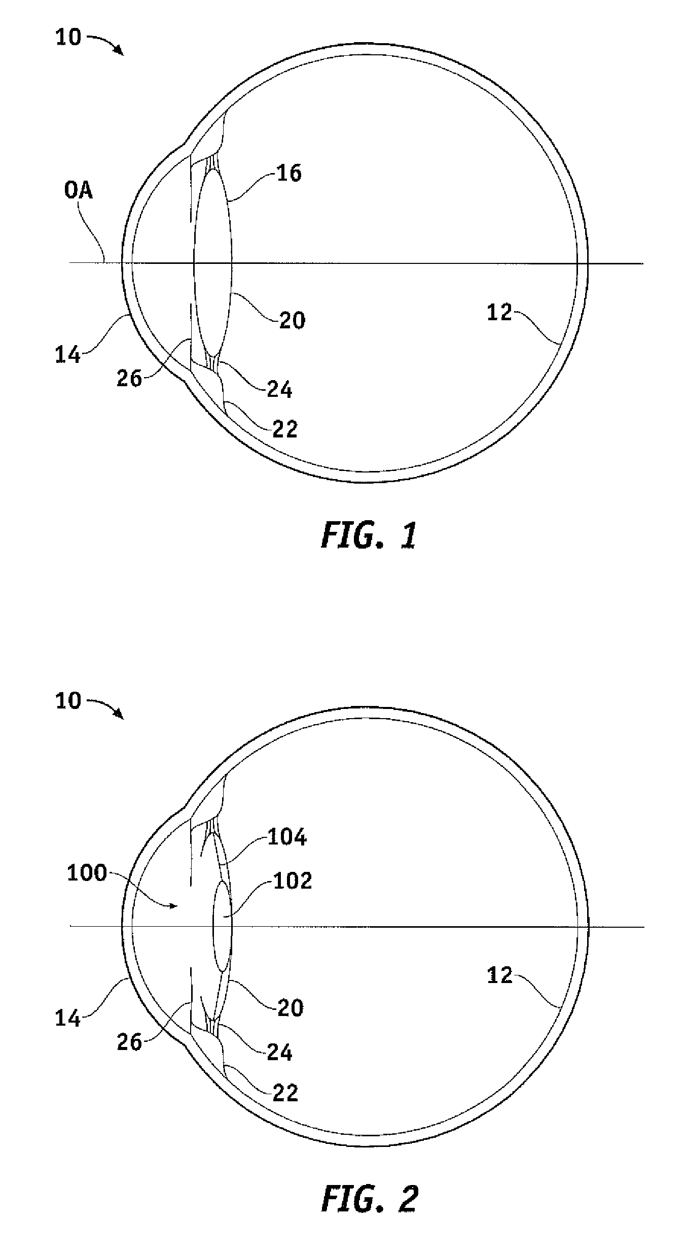
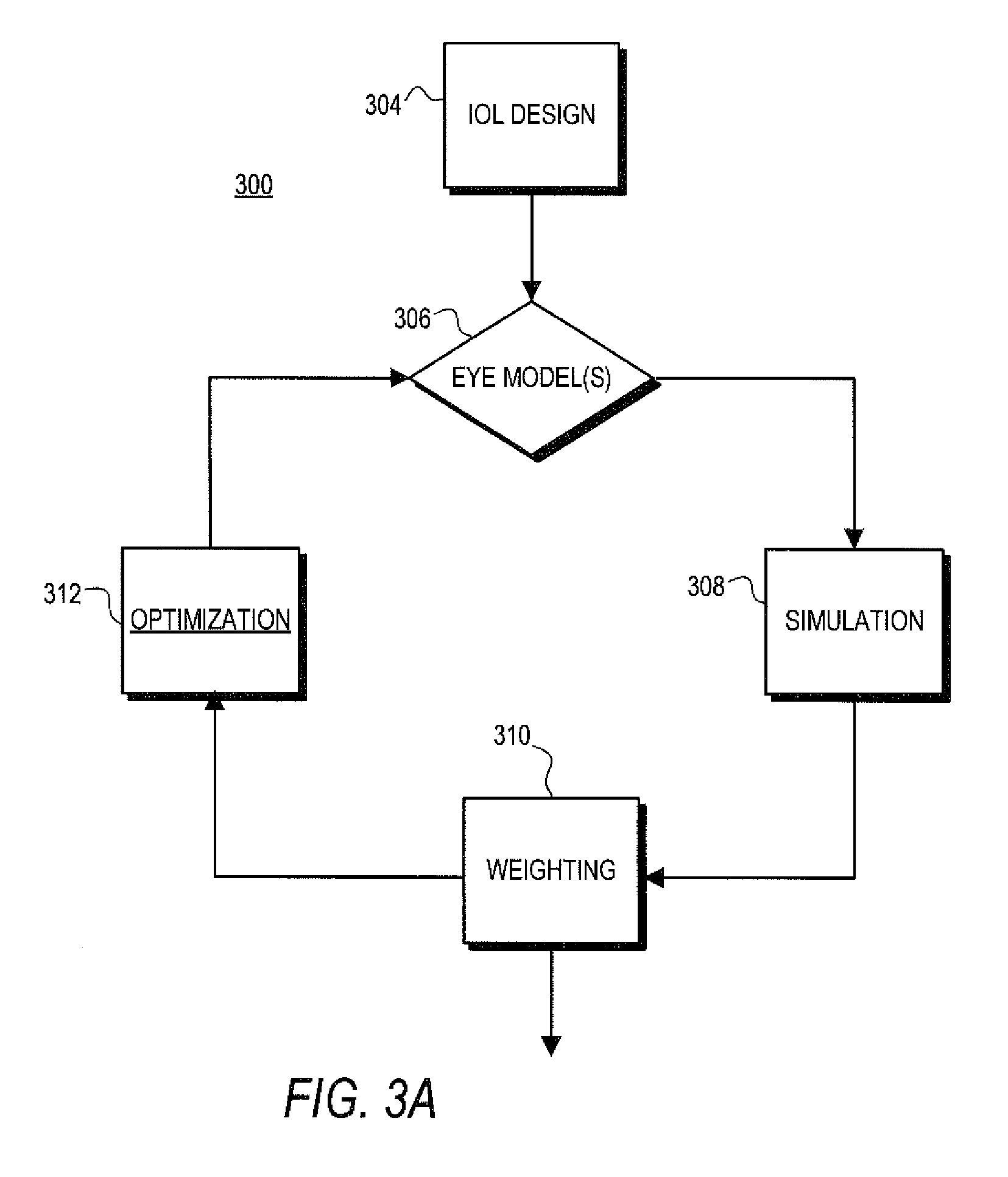

Image

  • Apparatus, system and method for predictive modeling to design, evaluate and optimize ophthalmic lenses
  • Apparatus, system and method for predictive modeling to design, evaluate and optimize ophthalmic lenses
  • Apparatus, system and method for predictive modeling to design, evaluate and optimize ophthalmic lenses

Examples


Embodiment Construction

[0034]It is to be understood that the figures and descriptions of the present invention have been simplified to illustrate elements that are relevant for a clear understanding of the present invention, while eliminating, for the purposes of clarity, many other elements found in typical optical and optical simulation apparatuses, systems and methods. Those of ordinary skill in the art will recognize that other elements are desirable and / or required in order to implement the present invention. However, because such elements are well known in the art, and because they do not facilitate a better understanding of the present invention, a discussion of such elements is not provided herein.

[0035]The apparatus, system and method of the present invention may be predictive as to the performance of ophthalmic lenses, such as IOLs, in the eye under any of a variety of circumstances, and with respect to any of a variety of ocular conditions and eye types, and may provide for improved performance...


PUM


Abstract

An apparatus, system and method for predictive modeling to design, evaluate and optimize ophthalmic lenses is disclosed. Ophthalmic lenses may include, for example, contacts, glasses or intraocular lenses (IOLs). The apparatus, system and method may include a design tool for designing a lens for implantation in an eye having a plurality of characteristics, a simulator for simulating performance of the lens in at least one modeled eye having the plurality of characteristics, at least one input for receiving clinical performance of the lens in the eye having the plurality of characteristics, a comparator for comparing outcomes of the clinical performance and the simulated performance, and an optimizer for optimizing a subsequent one of the outcome of the clinical performance responsive to modification of the lens in accordance with modification to the simulated performance.

Description

CROSS-REFERENCE TO RELATED APPLICATION[0001]N / ABACKGROUND OF THE INVENTION[0002]1. Field of the Invention[0003]The present invention is directed to lens design and, more particularly, to an apparatus, system and method for predictive modeling to design, evaluate and optimize ophthalmic lenses.[0004]2. Description of the Background[0005]Visual acuity is the clarity of vision, and more specifically is the spatial resolving power of a visual system. Visual acuity is thus the spatial level of detail that can be resolved by the visual system, and may be limited by physiological factors of the patient, such as optical factors within the eye and / or neural factors. Typically, visual acuity is heuristically obtained in an ophthalmic medical practice by presentation of a letter chart to the patient. Visual acuity may be calculated in accordance with the spatial frequency at which the eye's modulation transfer function (MTF) intersects with its neural threshold function (NTF).[0006]The optical...

Claims


Application Information

Patent Timeline
Patent Type & Authority Patents(United States)
IPC IPC(8): G06G7/48A61F2/16G02C7/02G02C7/04G02C7/06
CPCG02C7/02G02C7/04G02C7/041G02C7/06A61F2/16A61B3/0025A61F2240/002G02C7/024
Inventor WEEBER, HENDRIK, A.
Owner AMO GRONINGEN
Why Eureka
Eureka Blog
Learn More