
Trim element

a technology of components and components, applied in the direction of roofs, pedestrian/occupant safety arrangements, cellulosic plastic layered products, etc., can solve the problem of low strength and achieve the effect of no increase in cos

Active Publication Date: 2014-10-07
FAURECIA INTERIEUR IND
View PDF6 Cites 0 Cited by
  • Summary
  • Abstract
  • Description
  • Claims
  • Application Information

AI Technical Summary

Benefits of technology

[0007]The object of the invention is to solve the above-mentioned problem in a manner which requires no additional production operation and therefore no increase in cost.
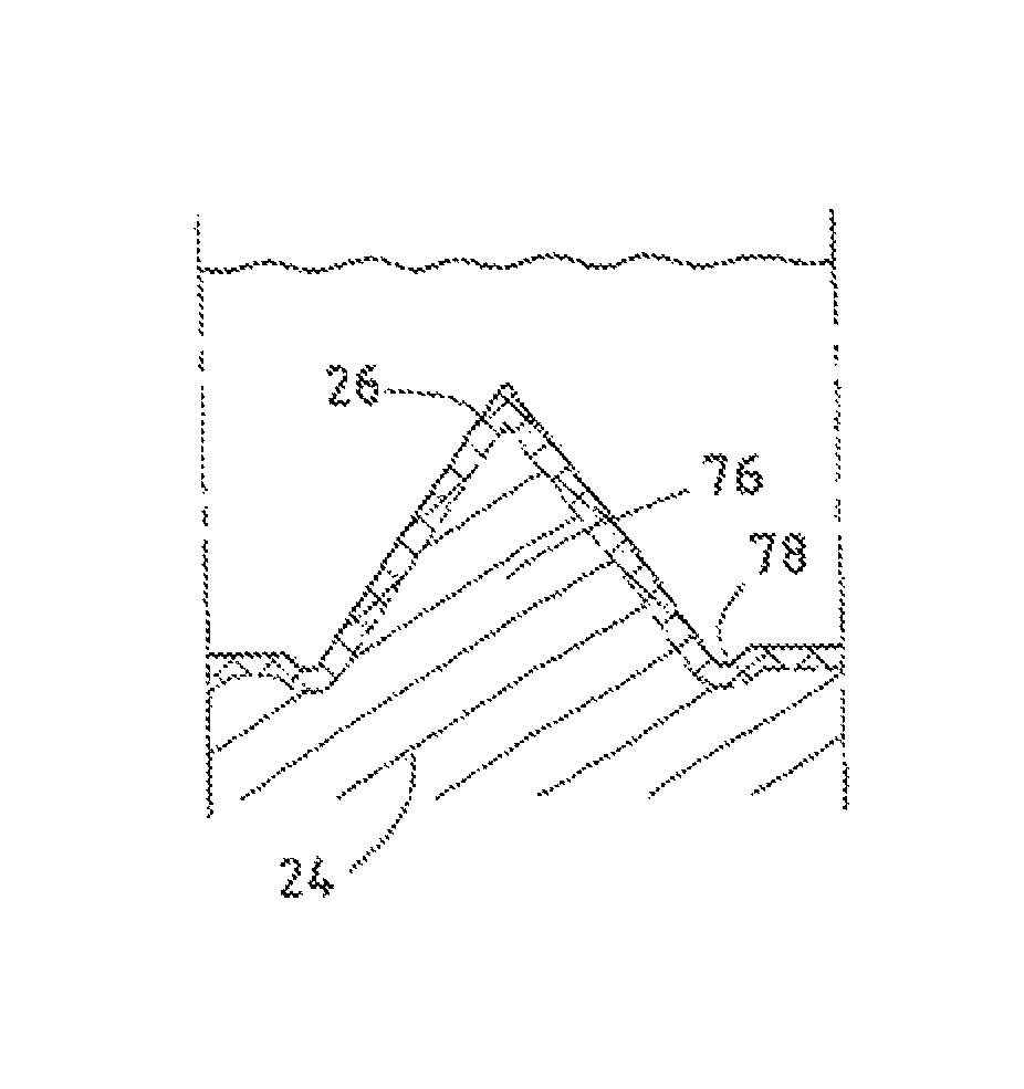
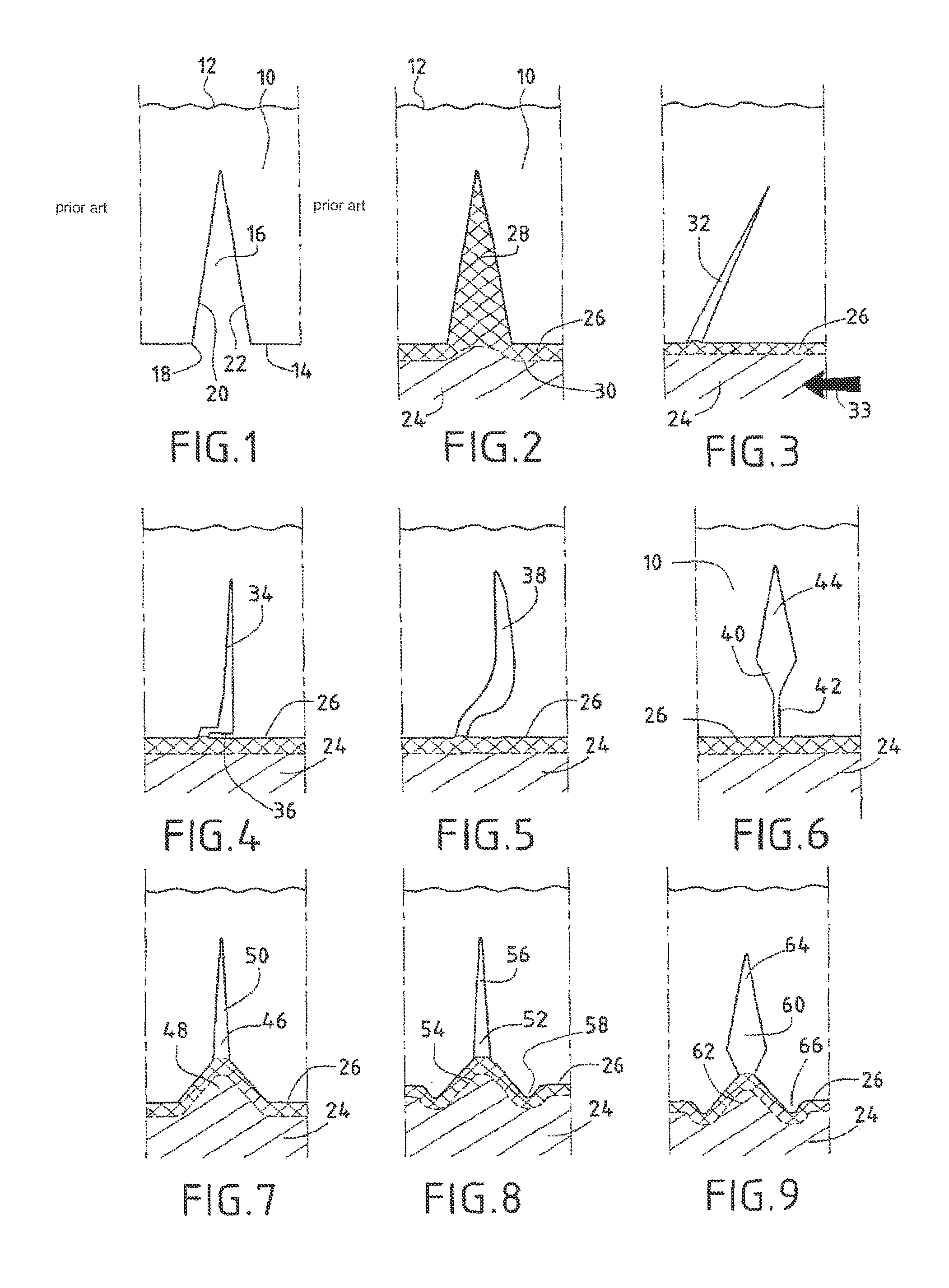
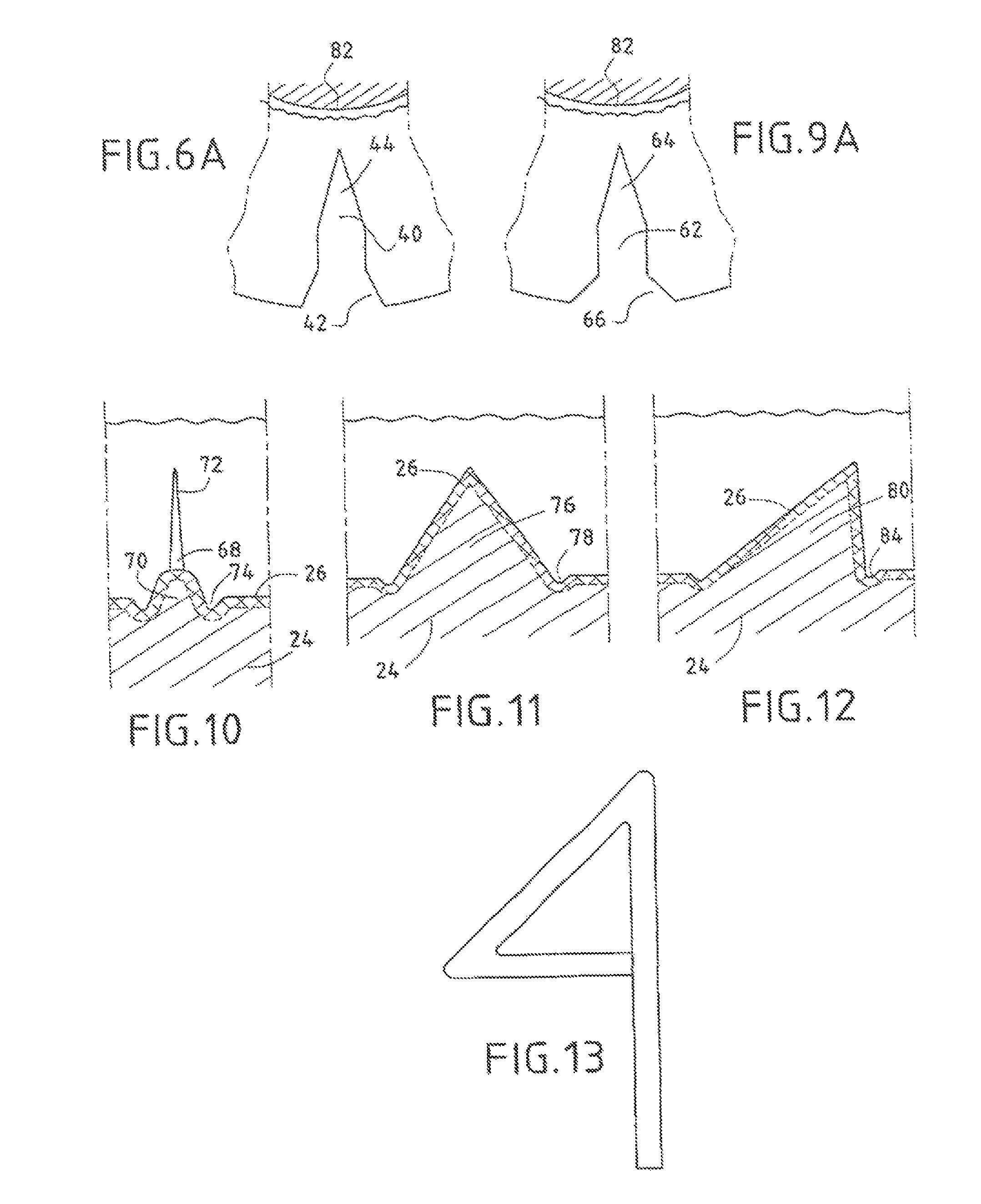
[0008]More precisely, according to the invention, the notch is provided with a configuration which prevents the formation of a bridge of extended thickness between the two sides of the notch. In a first shape, the configuration of the notch delimits an opening which is so narrow that, taking into account the wetting and surface tension properties of the skin and the plastics material used to shape the foam, the fluid plastics material practically does not penetrate into the notch. In a second shape, the notch is open to such a wide extent that the plastics material penetrates and the plastics material foam with a low level of strength is what fills the space of the notch and practically does not reduce the suitability of the notch for forming a preferred breaking zone.

Problems solved by technology

This method has the disadvantage of requiring a specific operation for forming a bridge on the opening of the notch, in a specific operation which is additional to the other production steps.
Furthermore, the component obtained must have a closure bridge which both has a low level of strength so as not to impede the tearing of the skin when an airbag is operated and is also sufficiently strong to withstand the various handling operations between the production thereof and the foaming operation inside a mould.

Method used


Image

  • Trim element
  • Trim element
  • Trim element

Examples


Embodiment Construction

[0026]FIG. 1 is a cross-section through a skin at the location of a notch. More precisely, a skin 10 having a visible face 12, having, for example, a grain, also has an inner face 14 on which a notch 16 opens via an opening 18. The notch has a V-shape which is delimited by two sides 20 and 22.

[0027]When an interior trim component is produced with this skin which delimits one side of a moulding cavity, a plastics material which is intended to form a foam is introduced at the side of the inner face 14 of the skin 10. Since the opening 18 of the notch is relatively large, the fluid plastics material can easily penetrate practically as far as the base of the notch. When the foaming operation is complete, the interface between the foam 24 which is normally flexible, and the inner surface 14 of the skin comprises a connection layer 26 which practically forms no foam and which constitutes a type of continuous film which is practically in constant contact with the inner surface 14 of the sk...


PUM

PropertyMeasurementUnit
angleaaaaaaaaaa
thicknessaaaaaaaaaa
widthaaaaaaaaaa

Abstract

A trim element having a visible side (12) formed of a skin (10), the element includes a skin (10) laid on a plastic foam (24) bonded to the skin by a continuous bonding layer (26) formed spontaneously at the skin-foam interface during the foaming operation, the skin (10) has a preferential rupture initiator comprising at least one scored feature. Throughout the region in which the scored feature lays, the bonding layer (26) is in contact only with the skin (10) and the foam (24), and, at the scored feature and in the direction of the thickness of the skin, the bonding layer (26) is laid over the opening with a thickness very much smaller than the depth of the scored feature.

Description

CROSS REFERENCE TO RELATED APPLICATIONS[0001]This application is a division of copending application Ser. No. 12 / 096,434 filed on Sep. 29, 2008; which is the 35 U.S.C. 371 national stage of International application PCT / FR2006 / 002639 filed on Dec. 4, 2006; which claims priority to French application 0512363 filed on Dec. 6, 2005. The entire contents of each of the above-identified applications are hereby incorporated by reference.FIELD OF THE INVENTION[0002]The invention relates to a trim component, substantially for the interior trim of a motor vehicle, having a visible face which is formed by a skin which is arranged on a layer of plastics material foam, and a device which is intended to form the notches in the skin for a trim component and a method for producing a trim component.[0003]Such trim components are used in order to form a specific number of surfaces, and in particular surfaces below which airbags are concealed. In this application, it is commonplace to delimit, in the ...

Claims


Application Information

Patent Timeline
Patent Type & Authority Patents(United States)
IPC IPC(8): B32B5/14B29C67/20B60R13/02B29C70/84B60R21/2165
CPCB60R13/02B29C70/84B60R2013/0287B60R21/2165Y10T428/24273Y10T428/24996Y10T428/24777Y10T428/249989
Inventor BAUDOUIN, IVANBEAUPERE, STEPHANEDERVOUT, ERICVAUPRE, FRANCOIS
Owner FAURECIA INTERIEUR IND
Learn More