Surgical instrument
a surgical instrument and distal end technology, applied in the field of surgical instruments, can solve the problems of reducing dexterity associated with a remote access by long instruments, unable to bend the distal end of the instrument to optimally orient the forceps relative to the practitioner, and the major application limitation of laparoscopic surgical tools, so as to simplify the manufacturing of instruments and control the effect of instruments
- Summary
- Abstract
- Description
- Claims
- Application Information
AI Technical Summary
Benefits of technology
Problems solved by technology
Method used
Image
Examples
first embodiment
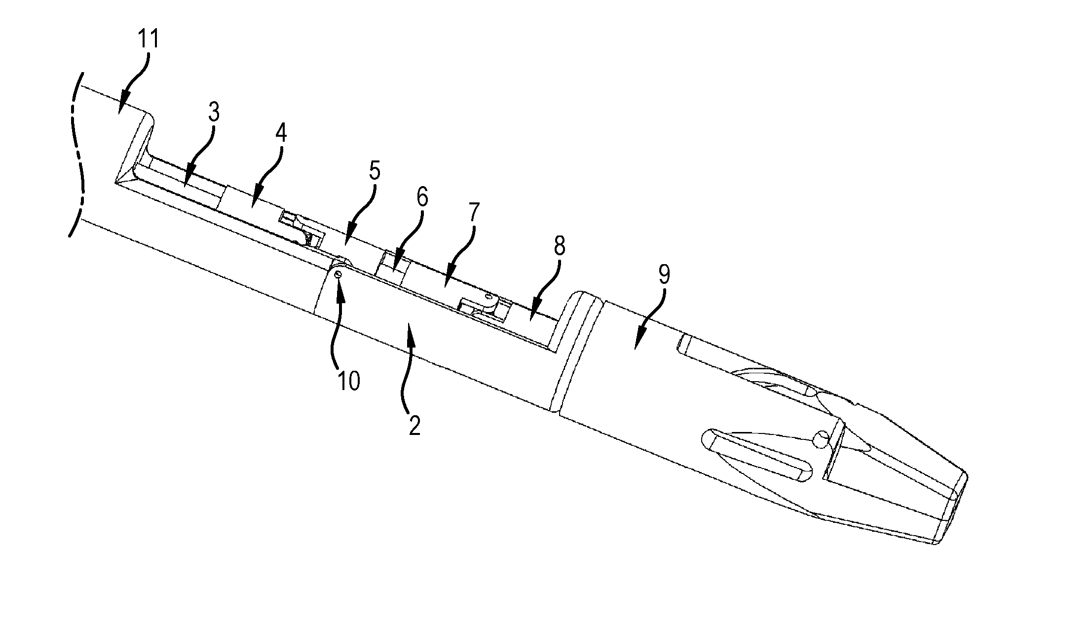
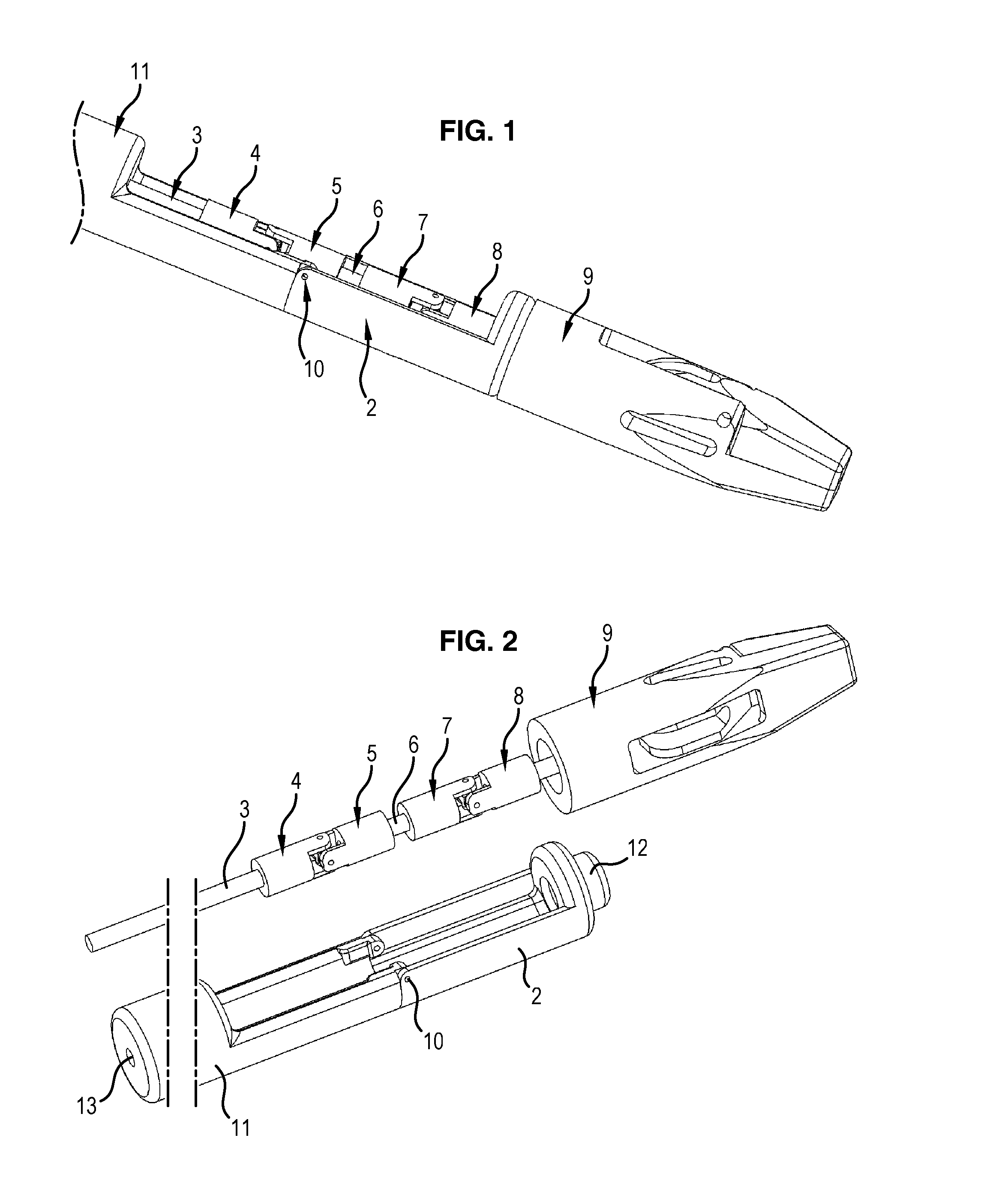
[0053]In reference to FIGS. 1 and 2, we will describe a surgical instrument according to the invention.
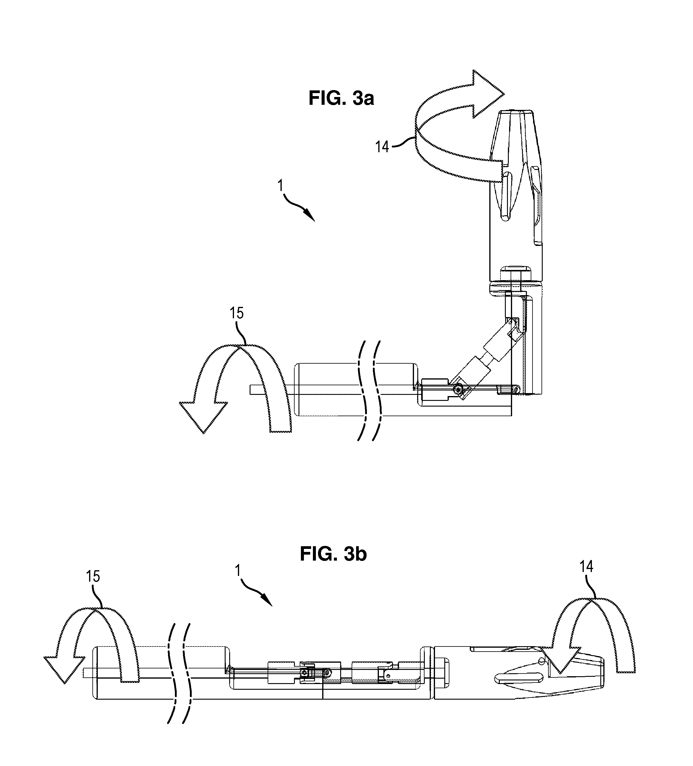
[0054]FIG. 1 illustrates the distal part of a surgical instrument 1 according to a first embodiment of the invention. The surgical instrument 1 comprises an elongated arm 11, here in a cylindrical revolution shape according to a longitudinal axis (not shown). The elongated arm is hollow and has, on a distal part, an opening on a semi-circumference terminating longitudinally via linking means comprising an axis 10 substantially orthogonal to the longitudinal axis of the elongated arm 11 and extending according to a diameter of a section of said elongated arm 11. These linking means connect the elongated arm to a distal end 2 comprising, in this respect, complementary linking means. This forms a pivot joint between the elongated arm 11 and the distal end 2. The distal end 2 here is hollow, cylindrical in revolution in shape about an axis and open on a semi-circumference approximately...
second embodiment
[0060]In reference to FIGS. 4 and 5, a surgical instrument 100 according to the invention will now be described. The surgical instrument 100 according to the invention comprises an elongated arm 111, here cylindrical in revolution in shape according to a longitudinal axis (not shown). The elongated arm 111 distally comprises a base linking element 101 comprising an axis 110 substantially perpendicular to the longitudinal axis of the elongated arm 111. The elongated arm 111 further comprises a second linking element 102 comprising a bore 112 at a proximal end and an axis 110 similar to the axis 110 of the base linking element 101 and situated at a distal end of the second linking element 102. The second linking element 102 is mounted in rotation on the base linking element 101 by cooperation of the axis 110 of the base linking element 101 and the bore 112 of the second linking element 102, thus forming a pivot joint. The elongated arm 111 further comprises a third linking element 105...
third embodiment
[0064]In reference to FIGS. 8 and 9, a surgical instrument 200 according to the invention will now be described. The surgical instrument 200 according to the invention comprises an elongated arm 207, here cylindrical in revolution in shape according to a longitudinal axis (not shown). The elongated arm 207 is hollow and distally comprises a base linking element 201 hollow, comprising two lugs extending in the extension of the elongated arm 207 and opposite one another to define an axis 210 substantially perpendicular to the longitudinal axis of the elongated arm 207. The elongated arm 207 further comprises second hollow linking elements 202, 203 (also called intermediate linking elements), comprising two lugs extending in the extension of said second linking elements 202, 203 and opposite one another to define an axis 210 similar to the axis 210 of the base linking element 201 and located at a distal end of the second linking elements 202, 203. The second linking element 202 is moun...
PUM
 Abstract
Description
Claims
Application Information
 - R&D
- Intellectual Property
- Life Sciences
- Materials
- Tech Scout
- Unparalleled Data Quality
- Higher Quality Content
- 60% Fewer Hallucinations
Browse by: Latest US Patents, China's latest patents, Technical Efficacy Thesaurus, Application Domain, Technology Topic, Popular Technical Reports.
© 2025 PatSnap. All rights reserved.Legal|Privacy policy|Modern Slavery Act Transparency Statement|Sitemap|About US| Contact US: help@patsnap.com


