
Heat-dissipation structure for motor

a technology of heat dissipation structure and motor, which is applied in the direction of structural association, dynamo-electric machines, supports/encloses/casings, etc., can solve the problems of abnormal operation, high manufacturing cost, and poor heat dissipation effect of air vents, so as to achieve better heat dissipation effect and rapid heat dissipation

Active Publication Date: 2014-09-23
ZHONGSHAN BROAD OCEAN MOTOR MFG
View PDF12 Cites 2 Cited by
  • Summary
  • Abstract
  • Description
  • Claims
  • Application Information

AI Technical Summary

Benefits of technology

[0007]In view of the above-described problems, it is one objective of the invention to provide a heat-dissipation structure for a motor that has rapid heat dissipation, excellent heat dissipation effect, a simple structure, an attractive shape, and great universality.
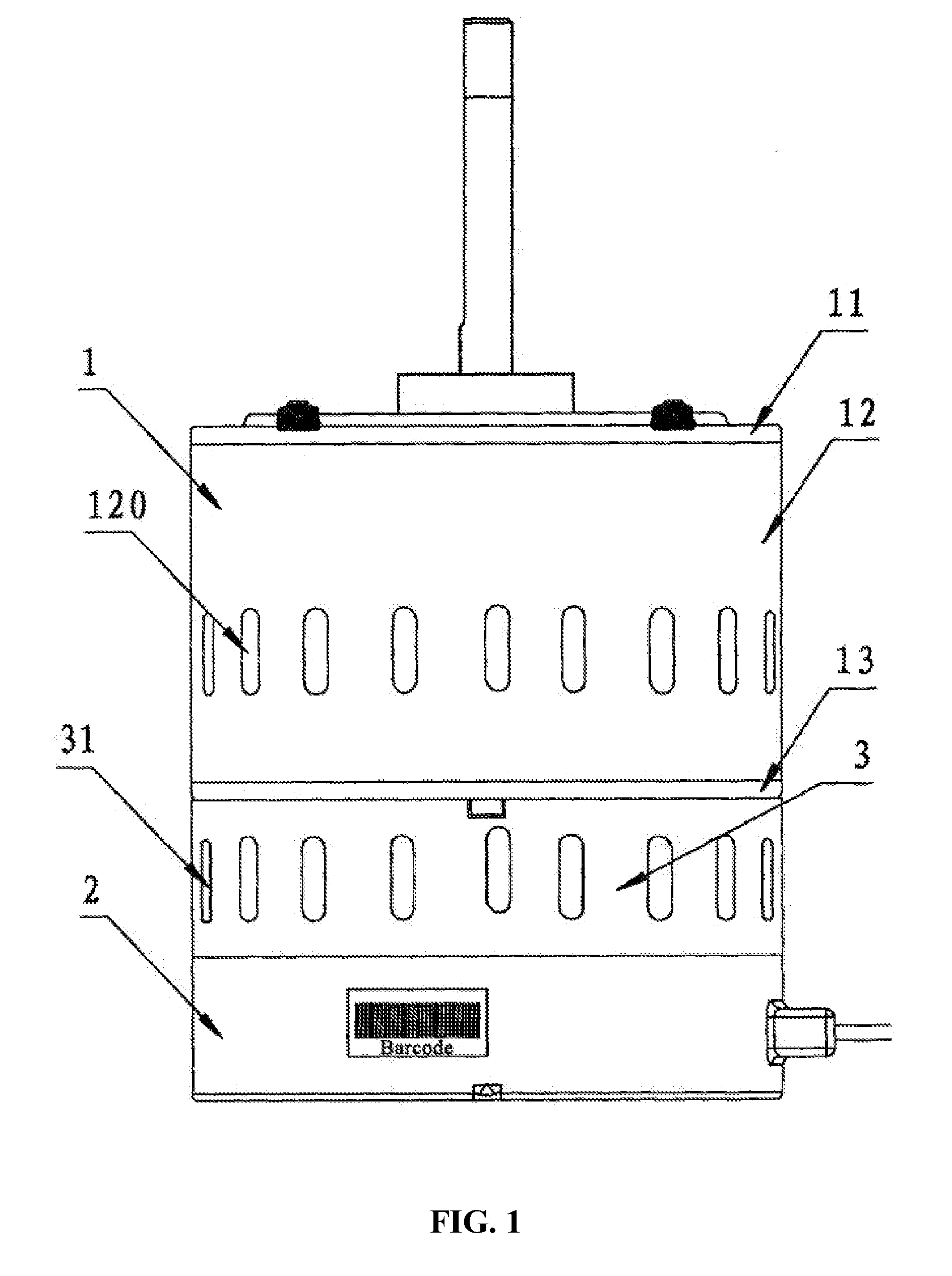
[0016]1) the heat-dissipation structure for a motor of the invention is provided with the coupling shell, of which one end is connected with the bottom of the motor shell and the other end is connected to the top of the control box and a plurality of air vents are arranged on the side wall of the coupling shell, thereby enlarging the inner space of the control box and achieve rapid heat dissipation and a better heat dissipation effect;
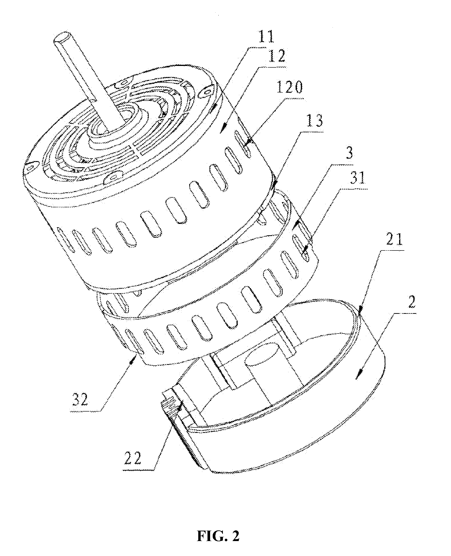
[0017]2) the motor shell comprises the front end cover, the columnar shell, and the rear end cover, wherein the columnar shell is arranged with the ventilation slot connecting to the cavity of the columnar shell and the coupling shell, thereby increasing air circulation inside the control box to achieve rapid heat dissipation and a better heat dissipation effect; and
[0018]3) the bottom of the rear end cover is arranged with the convex plate, sheathed with one end of the coupling shell; the top of the control box is in an open state with the step arranged along the edge and the other end of the coupling shell is sheathed on the step; the whole appearance is more attractive. As the coupling shell is a welded panel, no need to break the mould and thus it is economical. In addition, the height of the coupling shell is adjustable showing great flexibility and convenient use.

Problems solved by technology

Since conventional control boxes are a sealed structure, electronic components mainly dissipate heat by contacting the inner wall of the control box, having disadvantages of poor heat dissipation effect and abnormal operation.
However, it has the following disadvantages: apart from complicated manufacturing process and high manufacturing cost of moulds for air vents arranged along the circumferential direction of a control box, the air vents have a poor heat dissipation effect, unattractive appearance, poor universality and the circuit board's embedding process will be affected.

Method used


Image

  • Heat-dissipation structure for motor
  • Heat-dissipation structure for motor
  • Heat-dissipation structure for motor

Examples


Embodiment Construction

[0025]The invention is explained in further detail below with the aid of the examples and attached drawings.

[0026]As shown in FIGS. 1-5, a heat-dissipation structure for a motor in accordance with the invention comprises a motor shell 1, a control box 2, and a coupling shell 3. One end of the coupling shell 3 is connected to the bottom of the motor shell 1 and the other end is connected to the top of the control box 2 and a plurality of air vents 31 are arranged on the side wall of the coupling shell 3. The motor shell 1 comprises a front end cover 11, a columnar shell 12, and a rear end cover 13. The columnar shell 12 is arranged with a plurality of air vents 120, and the bottom of the rear end cover 13 is arranged with a convex plate 130, sheathed with one end of the coupling shell 3. The rear end cover 13 is arranged with a ventilation slot 131, respectively connecting to the cavity 110 of the columnar shell 11 and the cavity 30 of the coupling shell 3. The top of the control box...


PUM


Abstract

A heat-dissipation structure for a motor including a motor shell, a control box, and a coupling shell. One end of the coupling shell is connected to the bottom of the motor shell and the other end thereof is connected to the top of the control box and a plurality of air vents are arranged on a side wall of the coupling shell. The introduction of the coupling shell enlarges the inner space of the control box and achieves rapid heat dissipation and a better heat dissipation effect. The heat-dissipation structure features rapid heat dissipation, excellent heat dissipation effect, a simple structure, an attractive shape, and great universality.

Description

CROSS-REFERENCE TO RELATED APPLICATIONS[0001]Pursuant to 35 U.S.C. §119 and the Paris Convention Treaty, this application claims the benefit of Chinese Patent Application No. 201020557433.4 filed Oct. 1, 2010, the contents of which are incorporated herein by reference.BACKGROUND OF THE INVENTION[0002]1. Field of the Invention[0003]The invention relates to a heat-dissipation structure for a motor.[0004]2. Description of the Related Art[0005]A conventional DC brushless motor includes a motor and a control box. The control box is a cast aluminum piece directly mounted on the rear cover of the motor. Inside the control box, there is a circuit board, on which electronic components are mounted. Since conventional control boxes are a sealed structure, electronic components mainly dissipate heat by contacting the inner wall of the control box, having disadvantages of poor heat dissipation effect and abnormal operation.[0006]To solve the heat dissipation problem, air vents are usually arrang...

Claims


Application Information

Patent Timeline
Patent Type & Authority Patents(United States)
IPC IPC(8): H02K5/00H02K9/00H02K5/15H02K5/20H02K5/22H02K11/00
CPCH02K5/22H02K5/20H02K11/0073H02K5/15H02K11/33H02K5/207
Inventor TANG, SONGFA
Owner ZHONGSHAN BROAD OCEAN MOTOR MFG
Learn More