Antitheft device for a product display case
a technology for display cases and products, applied in the direction of lock applications, packaged goods types, instruments, etc., can solve the problems of requiring subsequent arrangement and maintenance of keys, customers usually hesitate to buy products, etc., and achieve the effect of high security effect, high security effect, and high security
- Summary
- Abstract
- Description
- Claims
- Application Information
AI Technical Summary
Benefits of technology
Problems solved by technology
Method used
Image
Examples
first embodiment
of the Self-Lock Means
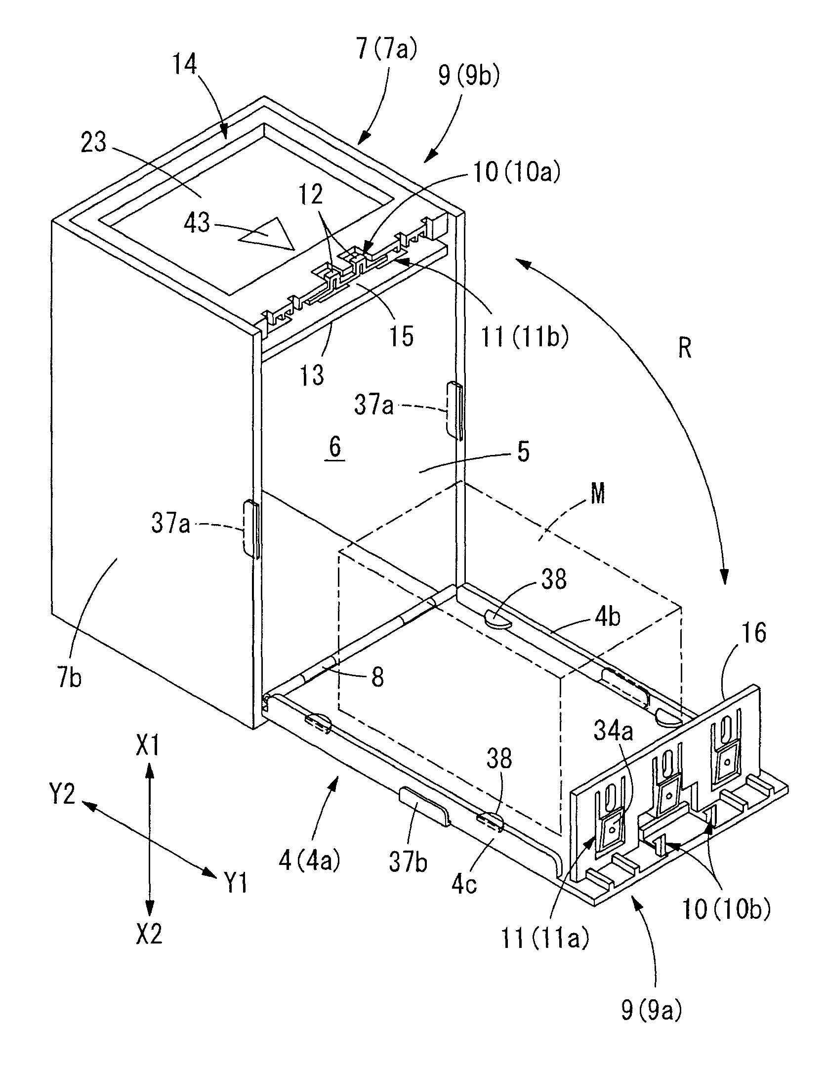
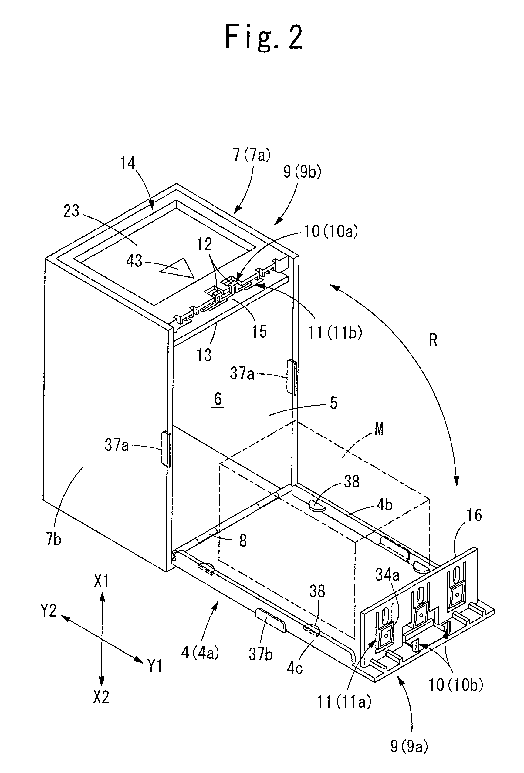
[0128]FIG. 12 to FIG. 17 show a first embodiment of the self-lock means. As shown in FIG. 12 and FIG. 13, the self-lock means 63 comprises a pair of lock members 64, 64 provided at both sides of the arm 34 which constitutes at least one latching member 11a selected among three latching members as shown (the central latching member 11a is selected in the illustrated example). The lock members 64, 64 are symmetrically arranged and are provided respectively with lock portions 65, 65 and resilient support means 66, 66 which support the lock portions 65, 65. The lock portions 65, 65 are faced to both sides of the arm 34 in a direction opposite to the Y1 direction so that the arm 34 is prevented from moving in the Y1 direction. Each resilient support means 66 comprises a resilient arm 67 extended from the interrupting wall 54 in the Y1 direction, and an operating arm 68 extended upward from the resilient arm 67. The lock portion 65 extends from the operating arm 68 i...
second embodiment
of the Self-Lock Means
[0139]FIG. 18 to FIG. 20 show a second embodiment of the self-lock means. In the second embodiment of the self-lock means 63, modifications are made in the above-mentioned first latching member 10a of the first lock means 10. Since the other features are same to those of the embodiment mentioned above, the same features are indicated by the same reference numerals in the drawings, and duplicate description will be omitted.
[0140]As shown in FIG. 18 and FIG. 19, the first latching member 10a of the first lock means 10 of projection-unlock-type, which is provided in the outer plate 14 of the case body 7a, comprises a rotary 70 provided with engaging portions 29b formed by apertures or recessions. The rotary 70 provides resilient axes 71 which connect the both ends of the rotary 70 to rib-like walls 21a, 21a extended from the plate wall 21. The rotary 70 and the axes 71 are formed integrally with the walls 21a, 21a by a flexible plastic so that the axes 71 comprise...
third embodiment
of the Self-Lock Means
[0148]FIG. 22 to FIG. 24 show a third embodiment of the self-lock means. Since the first lock means 10 of projection-unlock-type and the second lock means 11 of magnet-unlock-type are same to those mentioned about the embodiment shown in FIG. 1 to FIG. 10, the same features are indicated by the same reference numerals in the drawings, and duplicate description will be omitted.
[0149]The self-lock means 63 comprises a lock member 64b which is provided at the vicinity of a side edge of the arm 34 which is constituted by at least one second latching member 11a selected among three second latching members 11a (one of the two second latching members 11a located at both sides is selected in the illustrated example). The lock member 64b has a pin 73 which is slidably mounted on a bracket 72 of the standing plate 16 and is movable in the Z direction (in a direction along the width of the arm 34) which intersects the Y direction and the X direction.
[0150]The pin 73 provi...
PUM
 Abstract
Description
Claims
Application Information
 - R&D
- Intellectual Property
- Life Sciences
- Materials
- Tech Scout
- Unparalleled Data Quality
- Higher Quality Content
- 60% Fewer Hallucinations
Browse by: Latest US Patents, China's latest patents, Technical Efficacy Thesaurus, Application Domain, Technology Topic, Popular Technical Reports.
© 2025 PatSnap. All rights reserved.Legal|Privacy policy|Modern Slavery Act Transparency Statement|Sitemap|About US| Contact US: help@patsnap.com


