
Method for positioning a suspension body and magnetic suspension device using the method

a technology of magnetic suspension and positioning method, which is applied in the direction of magnetic holding device, magnetic body, instruments, etc., can solve the problems of difficult method, long time for people to try and difficult to position the suspension body to work over the base, etc., to achieve easy and quick positioning of the suspension body, easy to operate, and quick slide down

Inactive Publication Date: 2014-09-02
WANG XIAOBING +1
View PDF20 Cites 4 Cited by
  • Summary
  • Abstract
  • Description
  • Claims
  • Application Information

AI Technical Summary

Benefits of technology

The present invention provides a method and device for positioning a suspension body quickly and easily using a positioning auxiliary, such as a magnetic suspension device. This makes it faster and easier to suspend the suspension body in its work position, which improves its use efficiency. The method can also reduce the cost of the magnetic suspension device.

Problems solved by technology

The suspension body is artistic while being suspended, but it is difficult to position the suspension body to work over the base.
This method is always difficult, especially for people who contact with the magnetic suspension device for the first time.
It will take a long time for people to try to position the suspension body, and sometimes it will even take half an hour to position the suspension body.
However, when merchandise is exhibited via magnetic suspension, the curious viewer might take down the suspension body.
It will take a long time for the viewer to position the suspension body again, which is not good for exhibiting the merchandise.

Method used


Image

  • Method for positioning a suspension body and magnetic suspension device using the method
  • Method for positioning a suspension body and magnetic suspension device using the method
  • Method for positioning a suspension body and magnetic suspension device using the method

Examples


Embodiment Construction

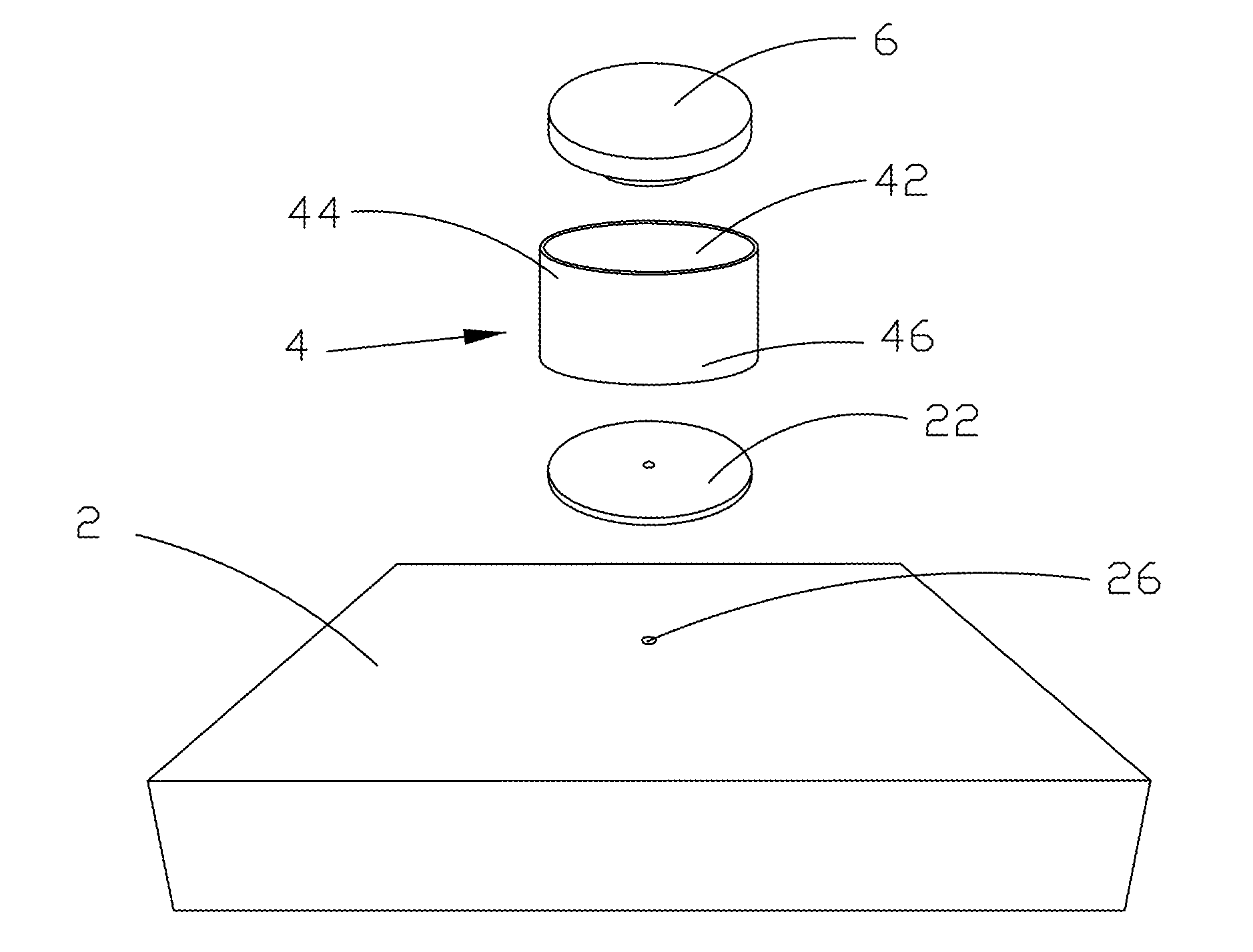
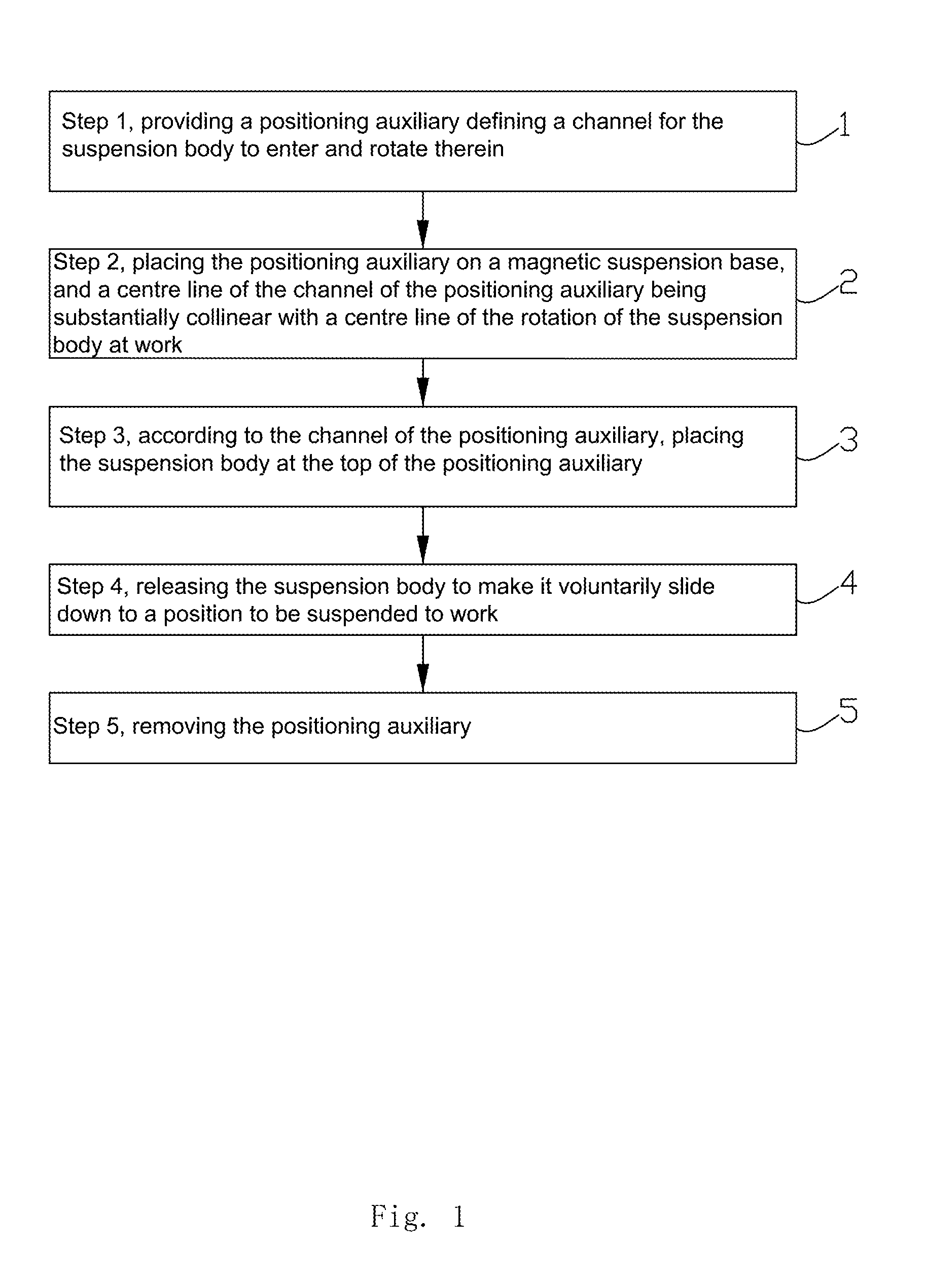
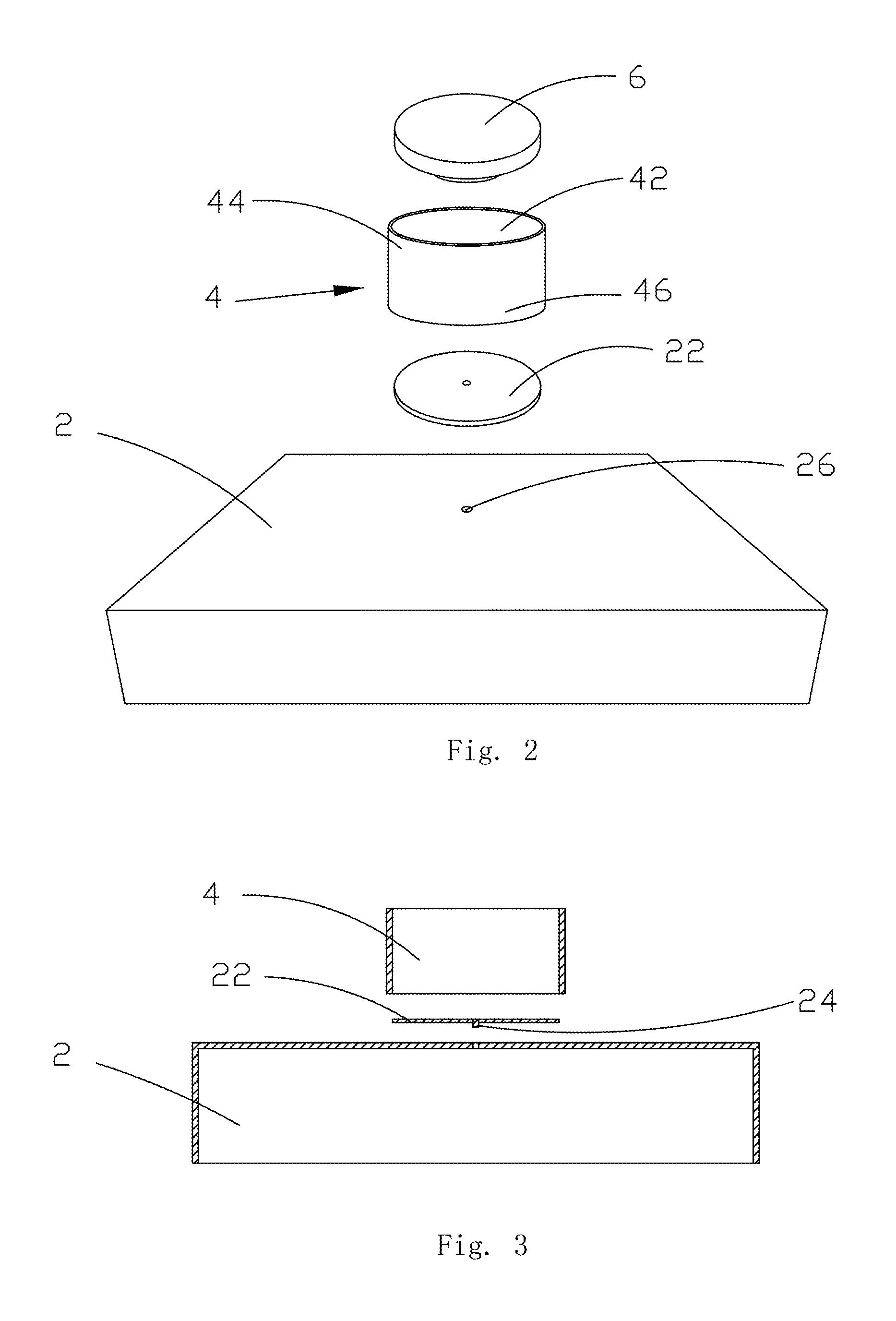
[0034]To further set forth the technical solution adopted by the present invention and the effects thereof, the present invention is described detailedly with reference to the following preferred embodiments and the accompanying figures.

[0035]As shown in FIG. 1, a method for positioning a suspension body of the present invention comprises the following steps:

[0036]Step 1, providing a positioning auxiliary defining a channel for the suspension body to enter and rotate therein;

[0037]Step 2, placing the positioning auxiliary on a magnetic suspension base, and a centre line of the channel of the positioning auxiliary being substantially collinear with a centre line of the rotation of the suspension body at work;

[0038]Step 3, according to the channel of the positioning auxiliary, placing the suspension body at the top of the positioning auxiliary; preferably being placed according to the centre line of the channel;

[0039]Step 4, releasing the suspension body to make it voluntarily slide d...


PUM

PropertyMeasurementUnit
rotationaaaaaaaaaa
magnetic forceaaaaaaaaaa
timeaaaaaaaaaa

Abstract

The present invention provides a method for positioning a suspension body and a magnetic suspension device using the method. The method comprises the following steps: step 1, providing a positioning auxiliary forming a channel for the suspension body to enter and rotate therein; step 2, placing the positioning auxiliary on a magnetic suspension base, and a center line of the channel of the positioning auxiliary being substantially collinear with a center line of the rotation of the suspension body at work; step 3, according to the channel of the positioning auxiliary, placing the suspension body at the top of the positioning auxiliary; step 4, releasing the suspension body to make it voluntarily slide down to a position to be suspended to work; step 5, removing the positioning auxiliary. The present invention can make the suspension body quickly slide down to be suspended at its work position by means of the positioning auxiliary, and so make the suspension body suspended normally, thereby greatly increasing the use efficiency.

Description

FIELD OF THE INVENTION[0001]The present invention relates to a method for positioning a suspension body and a magnetic suspension device using the method, particularly relates to a method for positioning a suspension body via a positioning auxiliary and a magnetic suspension device using the method.BACKGROUND OF THE INVENTION[0002]With the development of the aesthetical standard of people, a lot of products, such as handicraft articles, gifts, and publicity and exhibition appliances, adopt magnetic suspension technology, which has a comparatively good decorative effect and usability.[0003]A conventional magnetic suspension device comprises a base and a suspension body suspended over the base by magnetic force. A permanent magnet, a control circuit, a sensor, etc., are provided in the base, and a permanent magnet is provided in the suspension body. The suspension body is artistic while being suspended, but it is difficult to position the suspension body to work over the base. A conve...

Claims


Application Information

Patent Timeline
Patent Type & Authority Patents(United States)
IPC IPC(8): H01F7/02H01F1/00H01F41/02H02N15/00
CPCH02N15/00H01F41/02H01F7/0236Y10T29/49004
Inventor WANG, XIAOBINGLI, LIANGQING
Owner WANG XIAOBING
Learn More