
Communication antenna automatic orientation apparatus and method

a technology of automatic orientation and antenna, applied in the field of communication, can solve the problems of large range and huge implementation difficulty, and achieve the effects of improving service data rate and system capacity, improving user communication quality, and enlarge the coverage radius of ground base stations

Inactive Publication Date: 2014-08-19
ZTE CORP
View PDF6 Cites 4 Cited by
  • Summary
  • Abstract
  • Description
  • Claims
  • Application Information

AI Technical Summary

Benefits of technology

This solution improves user communication quality, increases service data rates, and enlarges the coverage radius of ground base stations while ensuring reliable handoff between service areas, addressing the limitations of current antennae systems.

Problems solved by technology

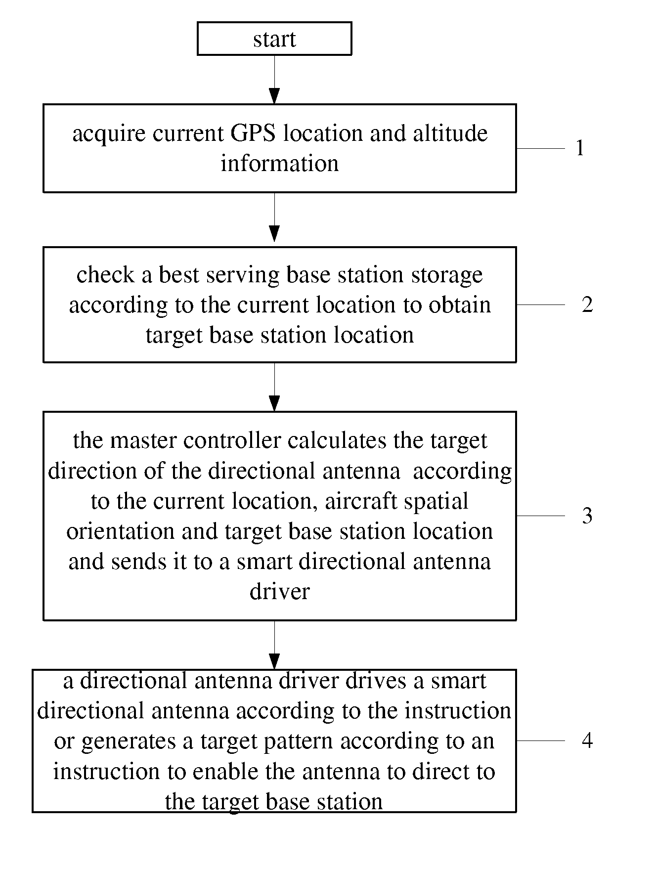
1. when an aircraft is flying, the geographical location thereof changes all the time and may cross the coverage range of a plurality of base stations, and the directional antenna must continuously direct to the best serving base station automatically and accurately;
2. if the smart antenna is required to be able to search the strongest serving base station direction on the ground automatically and rapidly, which of course is the most ideal solution, however, the required search angle range is very large, the horizontal plane is 360 degree and the vertical plane is approximate to 180 degree, which is approximate to a hemisphere, and the current stage of civilian communication technology still cannot reach this level, and in the foreseeable future, its implementation difficulty is still very huge due to the limitation of research costs and device volume;

Method used


Image

  • Communication antenna automatic orientation apparatus and method
  • Communication antenna automatic orientation apparatus and method
  • Communication antenna automatic orientation apparatus and method

Examples


embodiment i

Apparatus Embodiment I

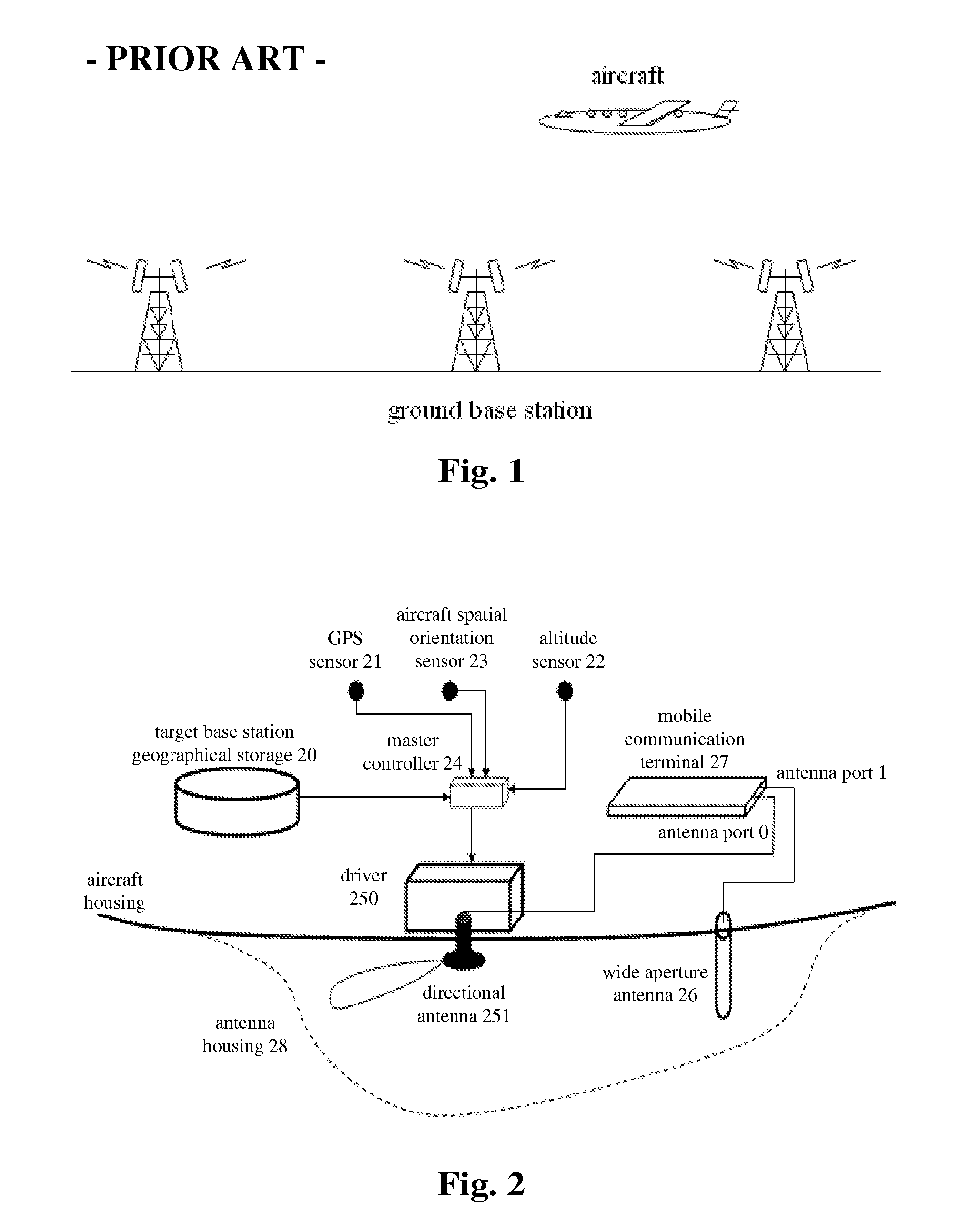
[0066]A communication antenna automatic orientation apparatus is provided according to the embodiments of the present invention, and FIG. 2 is a schematic diagram of a communication antenna automatic orientation apparatus according to apparatus embodiment I of the present invention, and as shown in FIG. 2, the communication antenna automatic orientation apparatus according to the embodiments of the present invention comprises: a target base station geographical storage 20 (i.e. the above best serving base station geographical storage), a sensor (including a GPS sensor 21 and an altitude sensor 22), an aircraft spatial orientation sensor 23, a master controller 24, an automatic antenna orientation system (not shown) (including a smart directional antenna driver 250 and a directional antenna 251), a wide aperture antenna 26, a mobile communication terminal 27 and an antenna housing 28. The communication antenna automatic orientation apparatus according to the emb...

embodiment ii

Apparatus Embodiment II

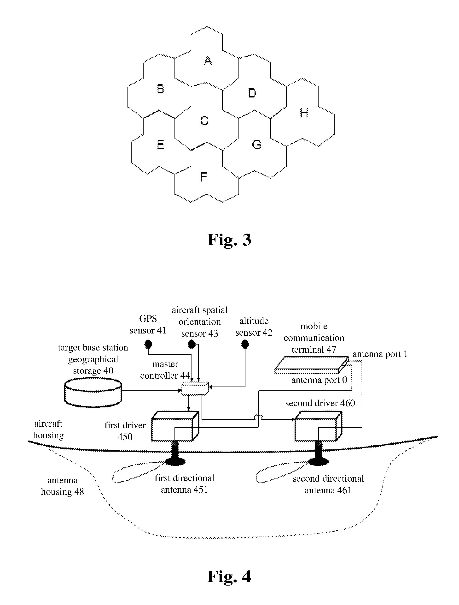
[0092]A communication antenna automatic orientation apparatus is provided according to the embodiments of the present invention, and FIG. 4 is a schematic diagram of a communication antenna automatic orientation apparatus according to apparatus embodiment II of the present invention, and as shown in FIG. 4, the communication antenna automatic orientation apparatus according to the embodiments of the present invention comprises: a target base station geographical storage 40 (i.e. the above best serving base station geographical storage), a sensor (including a GPS sensor 41 and an altitude sensor 42), an aircraft spatial orientation sensor 43, a master controller 44, a first automatic antenna orientation system (not shown) (including a first driver 450 and a first directional antenna 451), a second automatic antenna orientation system 46 (including a second driver 460 and a second directional antennal 461), a mobile communication terminal 47, and an antenna hous...

embodiment iii

Apparatus Embodiment III

[0121]A communication antenna automatic orientation apparatus is provided according to the embodiments of the present invention, and FIG. 5 is a schematic diagram of a communication antenna automatic orientation apparatus according to apparatus embodiment III of the present invention, and as shown in FIG. 5, the communication antenna automatic orientation apparatus according to the embodiments of the present invention comprises: a target base station geographical storage 50 (i.e. the above best serving base station geographical storage), a sensor (including a GPS sensor 51 and an altitude sensor 52), an aircraft spatial orientation sensor 53, a master controller 54, an electrically controlled beam smart antenna orientation system (including a driver 550, a first directional antenna 551 and a second directional antenna 552), a mobile communication terminal 56, and an antenna housing 57. The communication antenna automatic orientation apparatus according to the...


PUM


Abstract

The present invention discloses a communication antenna automatic orientation apparatus and method, wherein the apparatus comprises: a target base station geographical storage for storing the corresponding relation between the spatial location information on the air lane and the identifier of a target base station; a sensor for confirming current spatial location information of the aircraft; an aircraft spatial orientation sensor for confirming a current spatial orientation of the aircraft; a master controller for confirming a target direction of a directional antenna according to the current spatial location information, the corresponding relation and the current spatial orientation and sending an instruction carrying the target direction; an automatic antenna directional system for receiving the instruction and driving the directional antenna according to the target direction so as to enable the directional antenna to receive a signal from a ground base station in the target direction; a wide aperture antenna for receiving the signal from the ground base station in omni-direction; and a mobile communication terminal for processing the signal received by the wide aperture antenna and the signal received by the directional antenna.

Description

FIELD OF THE INVENTION[0001]The present invention relates to the communication field and, in particular, to a communication antenna automatic orientation apparatus and method.BACKGROUND OF THE INVENTION[0002]In relevant art, the dedicated cellular wireless communication network has already been able to provide service for aircrafts, such that people on the airplane can obtain popularized and economic mobile communication services which include voice service and packet data service. FIG. 1 is a schematic diagram of a ground base station covering an aircraft in relevant art. As shown in FIG. 1, the covering is basically implemented as follows: a certain number of base station networks with the suitable layout are built on the ground, the antennae inclines upwardly to cover a civilian aviation airspace, and the aircrafts are installed with mobile communication terminals and antennae thereof to communicate with the ground base stations.[0003]Currently, the mobile communication terminal ...

Claims


Application Information

Patent Timeline
Patent Type & Authority Patents(United States)
IPC IPC(8): H04B7/00H01Q1/12H01Q1/28H01Q3/00H04W84/06
CPCH01Q1/28H01Q1/125H04W84/06
Inventor XIE, WEIHAOZHOU, JIAHUIMA, YUE
Owner ZTE CORP
Learn More