Display device and method for driving same

a display device and display device technology, applied in the field of display devices and a method for driving the display device, can solve the problems of increasing the size of the liquid crystal panel, affecting the display effect, so as to reduce the luminance of the display and suppress the occurrence of at least on

Inactive Publication Date: 2014-08-05
SHARP KK
View PDF28 Cites 4 Cited by
  • Summary
  • Abstract
  • Description
  • Claims
  • Application Information

AI Technical Summary

Benefits of technology

[0026]As described above, according to the display device of the present invention and the driving method of the display device, an image signal to be supplied to a display element included in the area where the light guide element is provided is corrected in accordance with detected environment illuminance.
[0027]Accordingly, it is possible to suppress occurrence of at least one of a reduction in luminance of display of a light guide element portion and a color shift. This produces an effect that it is possible to carry out display also in the frame area while suppressing at least one of a difference in luminance and a difference in chromaticity between the display area where the display elements are disposed and the frame area where no display element is disposed.

Problems solved by technology

However, an increase in size of a liquid crystal panel poses many technical restrictions.
However, since each of the display devices has a frame region, the attempts cause a problem that seams between the plurality of display devices are visible.
This problem is not a problem specific to liquid crystal display devices, but is a problem common to direct-view-type display devices such as a PDP and an organic EL display device.

Method used


Image

  • Display device and method for driving same
  • Display device and method for driving same
  • Display device and method for driving same

Examples


embodiment 1

[0070][Embodiment 1]

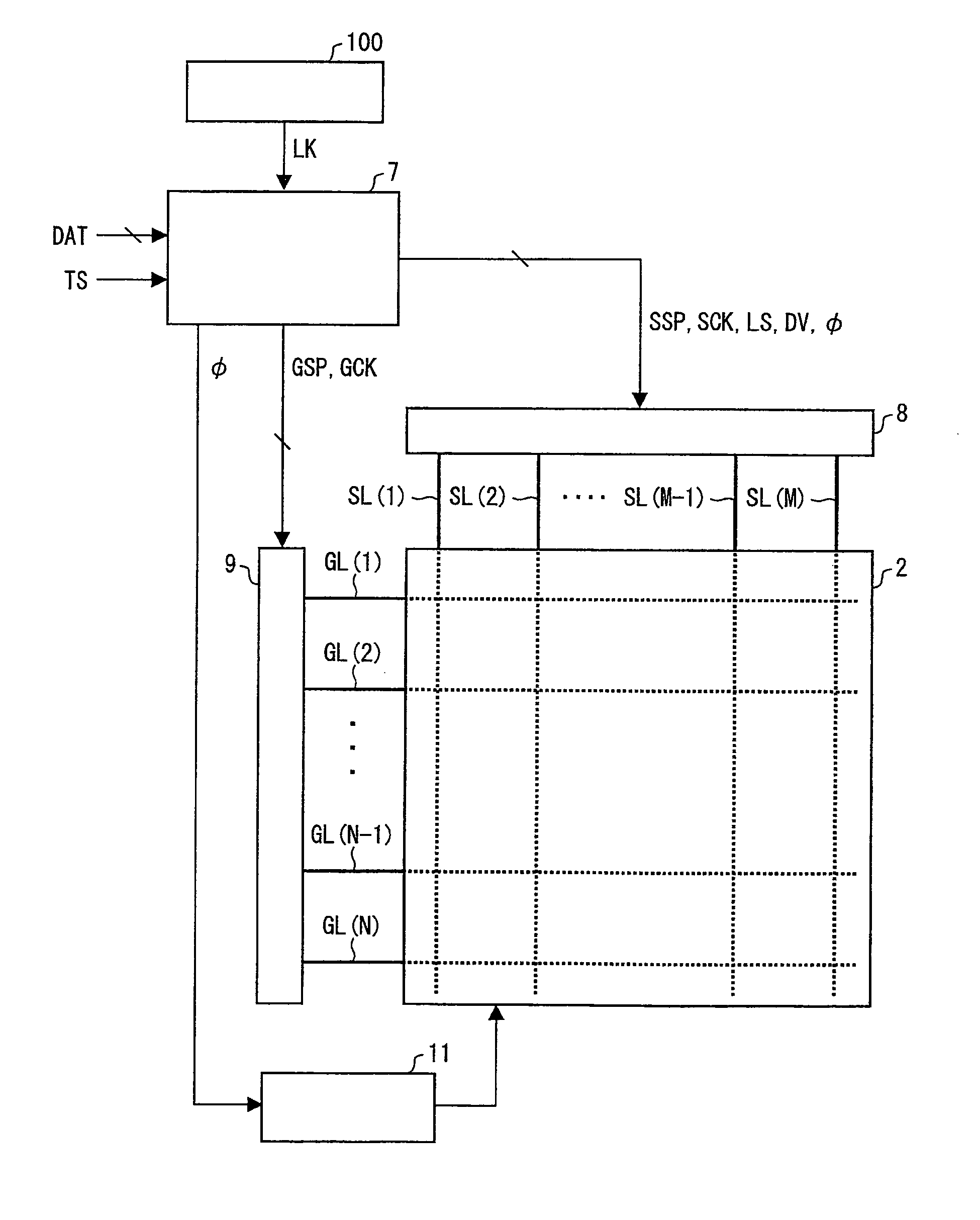
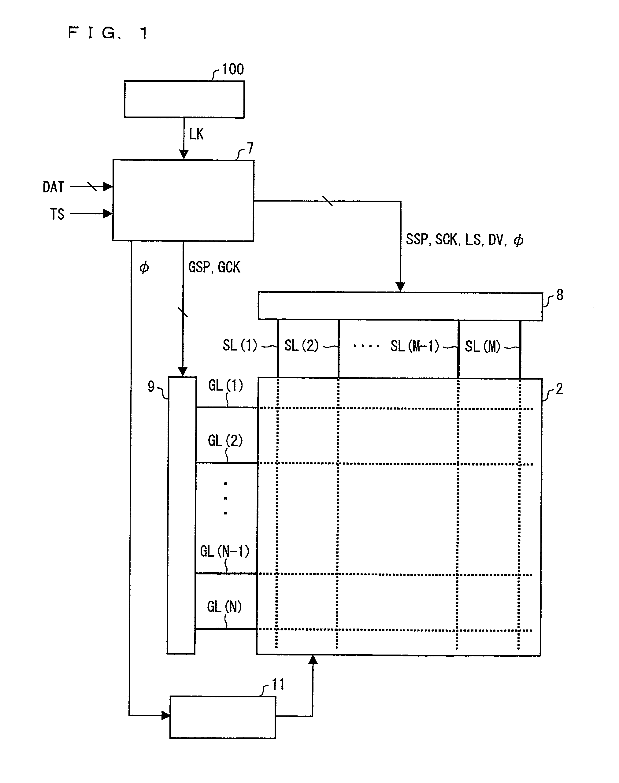
[0071]An embodiment of the present invention is described below with reference to FIGS. 1 through 9. Note that dimensions, materials, shapes, relative positions etc. of the constituent members described in the present embodiment are cited merely by way of example and without limitation, unless otherwise specified.

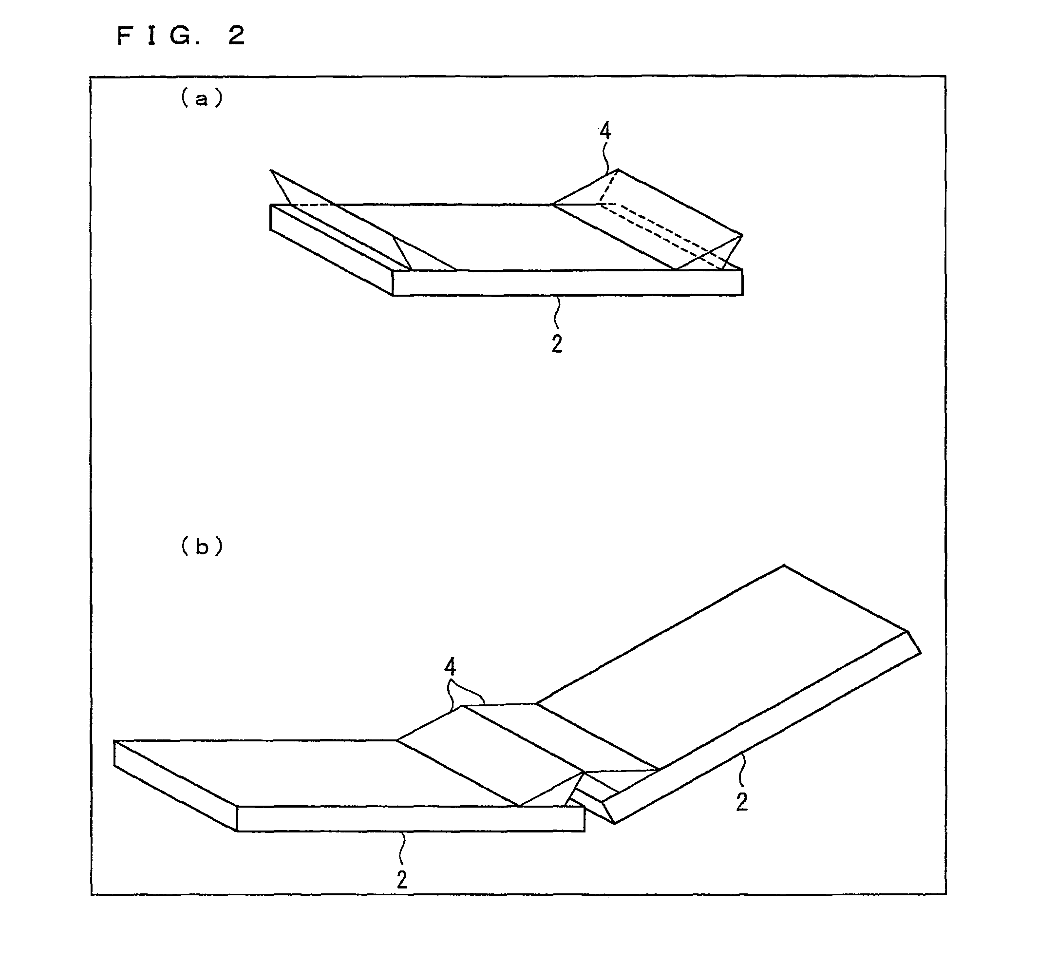
[0072]FIG. 2 is a perspective view schematically illustrating an appearance of a display device of the present embodiment. Embodiment 1 deals with a case where the display device is a liquid crystal display device, but is not limited to this. Each of the liquid crystal display devices shown in (a) and (b) of FIG. 2 includes a liquid crystal display panel(s) 2 and light guide elements 4. The liquid crystal display device shown in (a) of FIG. 2 includes a liquid crystal display panel 2 having a rectangular shape and two light guide elements 4 provided on the liquid crystal display panel 2 so as to be located in right and left peripheral areas facing each o...

embodiment 2

[0141][Embodiment 2]

[0142]Another embodiment of the present invention is described below with reference to FIGS. 10 through 13. For convenience of description, constituent members having identical functions to those shown in the drawings of Embodiment 1 are given identical reference numerals, and are not explained repeatedly.

[0143]FIG. 10 is a plan view illustrating a display device 1. The display device 1 includes display panels 2, light guide elements 4, and a photosensor 100. The photosensor 100 can be provided in any position in the display device 1, as long as environment illuminance can be measured. FIG. 10 shows an example in which a single photosensor 100 is provided on an outer frame of a display panel 2. Alternatively, the photosensor 100 may be provided so as to be adjacent to a pixel formation section (display element) in a normal display area A1 of the display panel 2 or may be provided so as to be incorporated in a pixel formation section. In this case, the photosensor...


PUM


Abstract

Provided is a display device for carrying out seamless display so that a sense of strangeness is not given to a viewer or the sense of strangeness is reduced. In at least one embodiment, a display device includes a display panel on which a plurality of display elements are disposed in a matrix, the display panel having a frame area which is located at an end of the display panel and in which no display element is provided; a light guide element provided on the display panel, the light guide element changing a light path of part of light emitted from the plurality of display elements so that the part of light is guided to the frame area; a photosensor provided on the display panel, the photosensor detecting environment illuminance; an image signal correcting section which (i) corrects, in accordance with the environment illuminance detected by the photosensor, an image signal to be supplied to a display element included in an area where the light guide element is provided so that a reduction in luminance or coloring of display light of the image caused by the light guide element is reduced, and (ii) outputs a corrected image signal; and a driving section which drives the display element in accordance with the corrected image signal.

Description

TECHNICAL FIELD[0001]The present invention relates to a display device and a method for driving the display device. More specifically, the present invention relates to (i) a display device (hereinafter referred to as seamless display) in which a seamless screen is achieved with the use of a plurality of display panels and (ii) a method for driving the display device.BACKGROUND ART[0002]In recent years, there is an increasing demand for a light and thin display. Especially, active matrix type liquid crystal display devices using a large liquid crystal panel are in wide spread use. However, an increase in size of a liquid crystal panel poses many technical restrictions. In view of this, attempts have been conventionally made for seemingly increasing a size of a liquid crystal panel by combining a plurality of display devices.[0003]However, since each of the display devices has a frame region, the attempts cause a problem that seams between the plurality of display devices are visible....

Claims


Application Information

Patent Timeline
Patent Type & Authority Patents(United States)
IPC IPC(8): G09G5/00G09G3/30H04N13/04
CPCG09G3/30H04N13/0438G02F1/13336G02F1/133524G06F3/1446G09G3/20G09G3/3611G09G2300/026G09G2310/0232G09G2320/0242G09G2320/0285G09G2320/0673G09G2360/144H04N13/341
Inventor IMAMURA, KENTAROUYOSHIDA, SHIGETO
Owner SHARP KK
Why Eureka
Try Eureka