
Electrically heated smoking system having a liquid storage portion

a smoking system and liquid storage technology, applied in the direction of ohmic resistance heating, electric/magnetic/electromagnetic heating, tobacco, etc., can solve the problems of liquid vaporization, difficult for an unauthorized user to access the liquid by dismantling the mouthpiece, and the risk of liquid leakage from the liquid storage portion, etc., to achieve the effect of limiting the degradation of liquid and simple mouthpiece structur

Active Publication Date: 2014-08-05
PHILIP MORRIS USA INC
View PDF252 Cites 389 Cited by
  • Summary
  • Abstract
  • Description
  • Claims
  • Application Information

AI Technical Summary

Benefits of technology

The solution maintains high hygiene, reduces waste, and minimizes the risk of the heating element becoming clogged, ensuring efficient and consistent aerosol production while preventing cross-contamination between different liquids.

Problems solved by technology

Firstly, because the replaceable mouthpiece contains the at least one heating element, the liquid storage portion and the wick, all elements which are potentially in contact with the liquid are changed when the mouthpiece is replaced.
Secondly, the mouthpiece structure means that there is a low risk of leakage from the liquid storage portion, which is not the case for many of the electrically heated smoking systems of the prior art.
This prevents waste of the liquid, but also makes it difficult for an unauthorized user to access the liquid by dismantling the mouthpiece.
The liquid has a boiling point suitable for use in the electrically heated smoking system: if the boiling point is too high, the heating element will not be able to vaporize liquid at the second end of the capillary wick, but, if the boiling point is too low, the liquid may vaporize even without the heating element being activated.

Method used


Image

  • Electrically heated smoking system having a liquid storage portion
  • Electrically heated smoking system having a liquid storage portion
  • Electrically heated smoking system having a liquid storage portion

Examples


Embodiment Construction

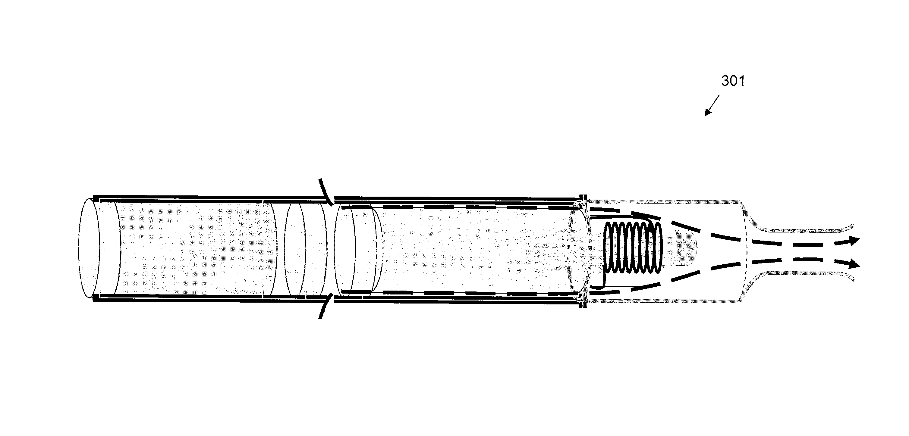
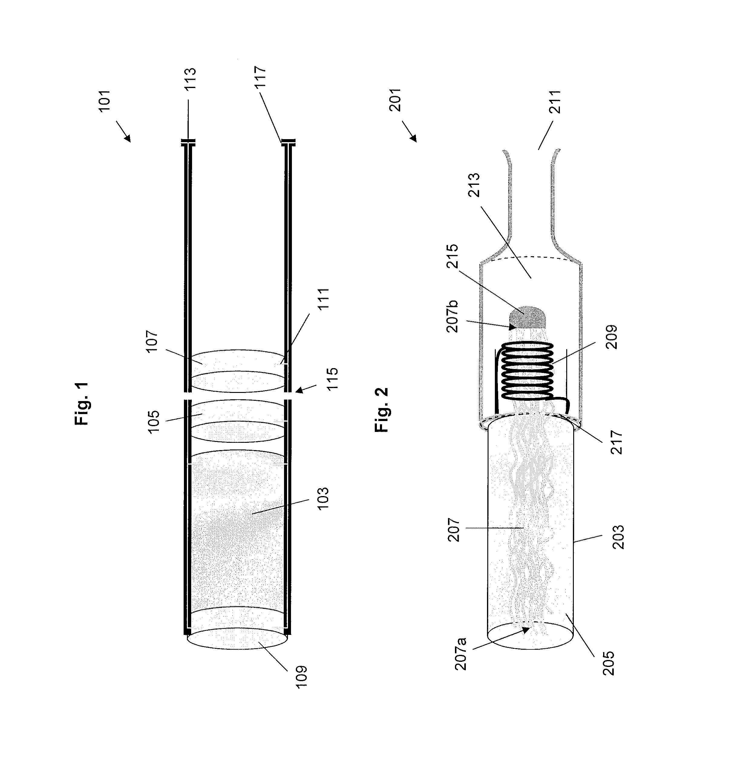
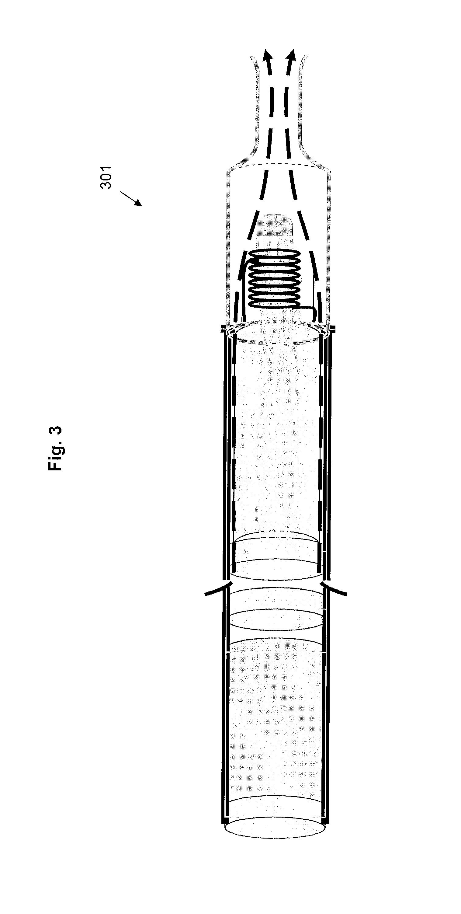
[0041]FIG. 1 shows a shell of an electrically heated smoking system according to one embodiment of the invention. The shell 101 comprises an electric power supply in the form of battery 103, electric circuitry in the form of circuitry 105 and puff detection system 107, a puff indicator 109, electrical connections 111, electrical contacts 113, air inlets 115 and a lock mechanism 117. The shell 101 is designed to engage with the mouthpiece 201 of FIG. 2.

[0042]FIG. 2 shows a mouthpiece of an electrically heated smoking system according to one embodiment of the invention. The mouthpiece 201 comprises a liquid storage portion in the form of cartridge 203 containing liquid 205, a capillary wick 207, a heating element in the form of heating coil 209, an air outlet 211 and an aerosol forming chamber 213. The first end 207a of the capillary wick 207 extends into the cartridge 203 and the second end 207b of the capillary wick 207 is surrounded by the heating coil 209. The mouthpiece also incl...


PUM


Abstract

An electrically heated smoking system includes a shell and a replaceable mouthpiece. The shell includes an electric power supply and electric circuitry. The mouthpiece includes a liquid storage portion and a capillary wick having a first end and a second end. The first end of the wick extends into the liquid storage portion for contact with liquid therein. The mouthpiece also includes a heating element for heating the second end of the capillary wick, an air outlet, and an aerosol forming chamber between the second end of the capillary wick and the air outlet. When the shell and mouthpiece are engaged or connected, the heating element is in electrical connection with the power supply via the circuitry, and a flowpath for air is defined from at least one air inlet to the air outlet via the aerosol forming chamber. In use, liquid is transferred from the liquid storage portion towards the heating element by capillary action in the wick. Liquid at the second end of the capillary wick is vaporized by the heating element. The supersaturated vapor created, is mixed and carried in the air flow from the at least one air inlet to the aerosol forming chamber. In the aerosol forming chamber, the vapor condenses to form an aerosol, which is carried towards the air outlet.

Description

CROSS-REFERENCE TO RELATED APPLICATION[0001]This application corresponds to European Application No. 08 251 579, filed Apr. 30, 2008, the entire contents of which are incorporated herein by this reference thereto.BACKGROUND OF THE INVENTION[0002]The present invention relates to an electrically heated smoking system for receiving an aerosol-forming substrate. In particular, the present invention relates to an electrically heated smoking system for receiving an aerosol-forming substrate, in which the aerosol-forming substrate is a liquid.[0003]A number of prior art documents, for example U.S. Pat. No. 5,060,671 (commonly assigned, the entire contents of which are incorporated herein by this reference thereto), U.S. Pat. No. 5,388,594 (commonly assigned, the entire contents of which are incorporated herein by this reference thereto), U.S. Pat. No. 5,505,214 (commonly assigned, the entire contents of which are incorporated herein by this reference thereto), U.S. Pat. No. 5,591,368 (comm...

Claims


Application Information

Patent Timeline
Patent Type & Authority Patents(United States)
IPC IPC(8): H05B3/02A61M15/06A24F40/10A24F40/44A24F40/485
CPCA24D3/18A24F47/008A24F40/44A24F40/10A24F40/485A24D1/14A61M15/06H05B6/36H05B6/108A24F40/46A24F40/42H05B3/0019A24F47/00H05B3/00
Inventor THORENS, MICHELFLICK, JEAN-MARCCOCHAND, OLIVIER YVES
Owner PHILIP MORRIS USA INC
Learn More