
Firearm sling assembly, related mechanisms and methods

a technology of slings and slings, applied in the field of single-point rifle slings, can solve the problems of inability to provide immediate firing access, inadvertent release of rifles from slings, and dangerous bungee designs, so as to prevent metal clanging, minimize noise, and prevent the effect of key disengagemen

Active Publication Date: 2014-08-05
SAFARILAND
View PDF6 Cites 10 Cited by
  • Summary
  • Abstract
  • Description
  • Claims
  • Application Information

AI Technical Summary

Benefits of technology

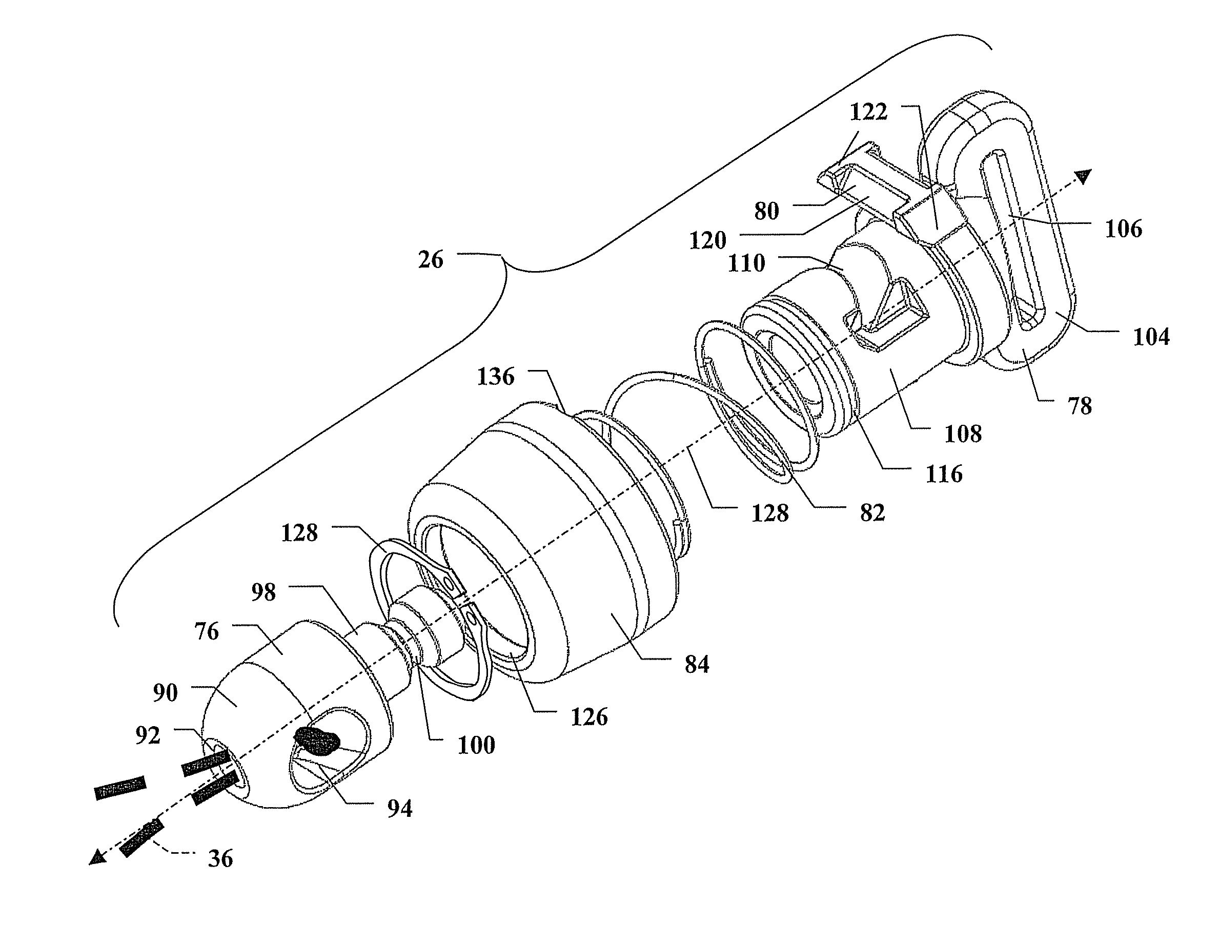
[0007]According to an aspect of the present invention, the quick-release mechanism includes a first element having a key groove defined therein, a second element having a key channel defined therein, the key channel extending between a first opening adjacent the key groove and a second opening away from the key groove, a key slidably disposed in the key channel and retractably engaging the key groove through the first opening, a biasing element acting between the key and second element to bias the key into engagement with the key groove, and a release element disposed on the second element and displaceable relative thereto to disengage the key from the key groove. The disengagement of the key from the key groove allows detachment of the first and second elements.
[0008]According to a further aspect of the present invention, all components of the sling assembly that would require operation in a tactical situation, or be subject to repeated contact with the firearm, metallic items on the user, or other metallic equipment, are formed from non-metallic materials to prevent metal clanging and minimize noise.
[0009]According to an additional aspect of the present invention, the sling assembly includes a locking element releasably engaging the release element to prevent disengagement of the key from the key groove.

Problems solved by technology

Although this sling design supported the rifle during long marches, it did not provide immediate firing access.
These bungee designs, however, have proven to be dangerous.
For example, a rifle carried hands-free can become snagged, resulting in the rifle inadvertently releasing from the sling.
This can result in the butt stock of the weapon forcefully impacting the operator's chin or other parts of his face.

Method used


Image

  • Firearm sling assembly, related mechanisms and methods
  • Firearm sling assembly, related mechanisms and methods
  • Firearm sling assembly, related mechanisms and methods

Examples


Embodiment Construction

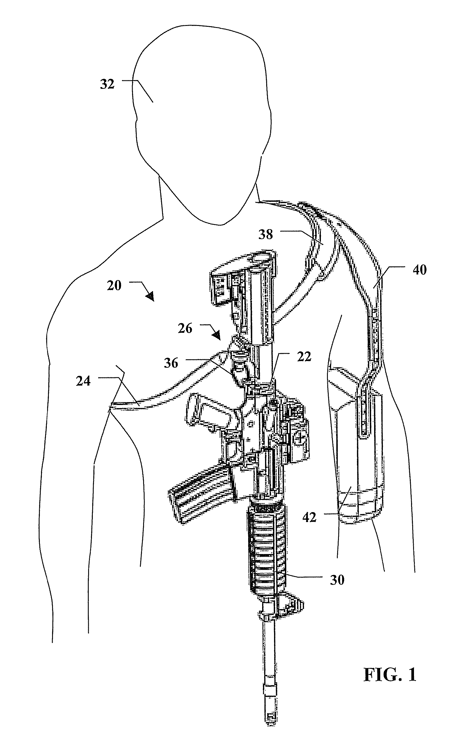
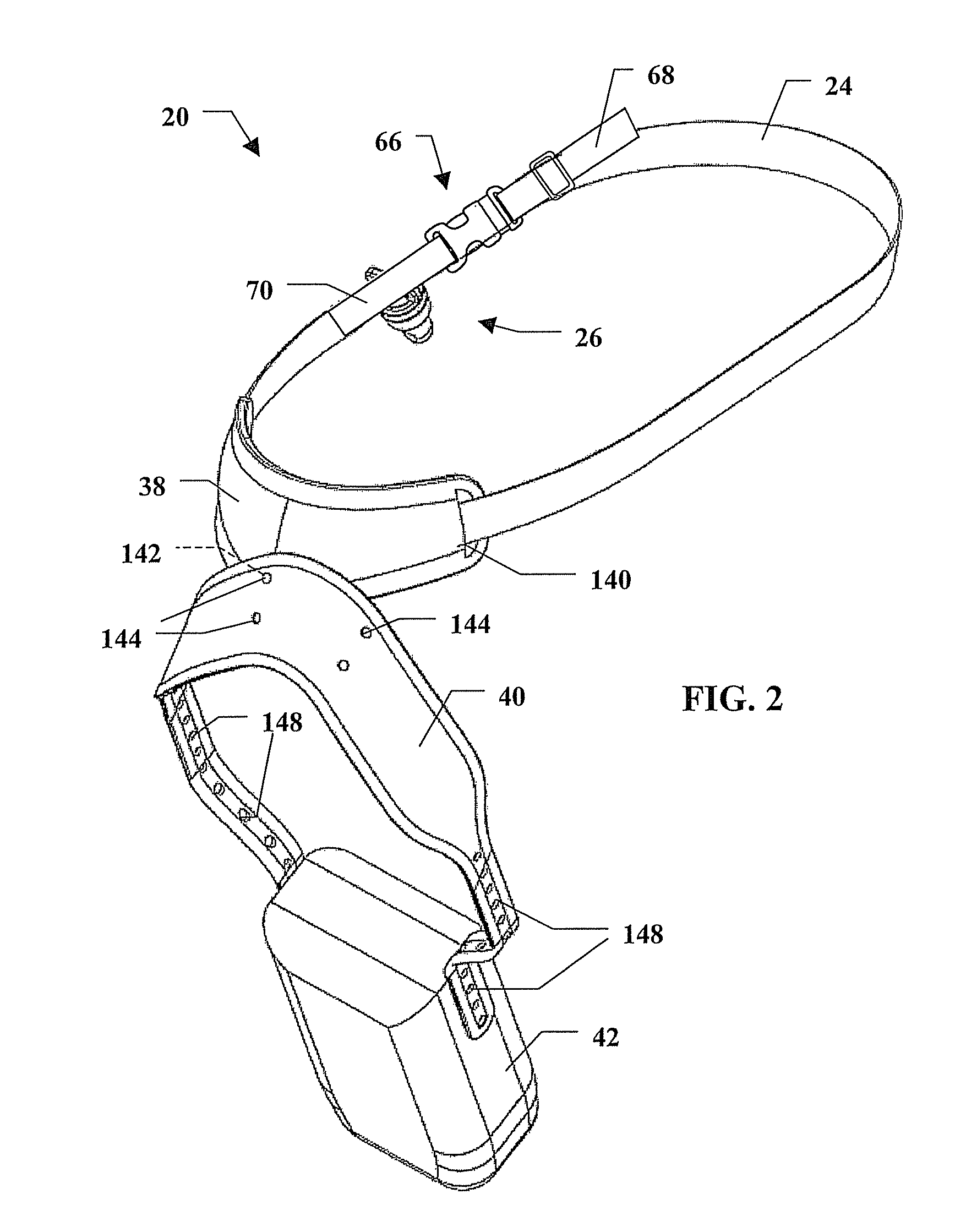
[0022]According to an embodiment of the present invention, referring to FIGS. 1 and 2, a firearm sling assembly 20 includes an anchor 22, a strap 24 and a quick-release mechanism 26. The anchor 22 is adapted for connection to a firearm 30, such as a rifle, and most preferably to the rifle stock rearward of the trigger. The strap 24 forms a single loop is adapted for wear on the shoulder of a user 32, extending over one shoulder and under the opposite shoulder. The quick-release mechanism 26 releasably attaches the anchor 22 to the strap 24. Preferably, a short cord 36 connects the anchor 22 with the quick-release mechanism 26. The sling assembly 20 further includes a shoulder pad 38 through which the strap 24 is slidably routed, an accessory strap 40 removably connected to the shoulder pad 38, and an accessory 42, such as a magazine holder, removably suspended from the accessory strap 40.

[0023]Although in FIG. 1 the firearm 30 is shown slung in a hands-free front position, allowing ...


PUM


Abstract

A firearm sling assembly includes an anchor adapted for connection to a firearm, a strap forming a single loop and adapted for wearing around a user's neck, and a quick-release mechanism releasably attaching the anchor to the strap. The quick-release mechanism includes a first element having a key groove defined therein, a second element having a key channel defined therein, the key channel extending between a first opening adjacent the key groove and a second opening away from the key groove, a key slidably disposed in the key channel and retractably engaging the key groove through the first opening, a biasing element acting between the key and second element to bias the key into engagement with the key groove, and a release element disposed on the second element and displaceable relative thereto to disengage the key from the key groove.

Description

CROSS-REFERENCE TO RELATED APPLICATION[0001]This application is the 371 National Stage of International Application No. PCT / US2009 / 056177 filed on Sep. 8, 2009, which claims the benefit of U.S. Provisional Application Ser. No. 61 / 094,665, filed on Sep. 5, 2008, the contents of which applications, are hereby incorporated by reference in their entirety.FIELD OF THE INVENTION[0002]The present invention relates to firearm slings, and more particularly, to single point rifle slings and their use.BACKGROUND OF THE INVENTION[0003]Rifle slings have been used by the military since the introduction of firearms in warfare. In the beginning, a sling was mainly necessary to support the weight of a weapon during long marches. A two-point sling, in which one end of an adjustable strap is attached to a forearm of a rifle and the other end is attached to a butt stock, became the most dominant design. An operator positioned the rifle over one shoulder toward his back, where it was carried hands-free....

Claims


Application Information

Patent Timeline
Patent Type & Authority Patents(United States)
IPC IPC(8): F41C23/02
CPCF41C33/002F41C23/02Y10T24/12
Inventor ROGERS, WILLIAM H.MCKENDRICK, MATTHEW E.
Owner SAFARILAND
Learn More