Processing method for concave-convex gear

a processing method and concave-convex gear technology, applied in the direction of gear teeth, gear teeth, gear-teeth manufacturing apparatus, etc., can solve the problem of difficult machining, and achieve the effect of increasing the ming gear and the concave-convex gear, reducing size, and increasing strength

Inactive Publication Date: 2014-07-15
JTEKT CORP
View PDF27 Cites 2 Cited by
  • Summary
  • Abstract
  • Description
  • Claims
  • Application Information

AI Technical Summary

Benefits of technology

[0024]With the invention according to claim 1 configured as described above, an NC machine tool is used to make it possible to machine the concave teeth of the concave-convex gear. That is, the same NC machine tool may be used to machine concave-convex gears having various shapes. Furthermore, movement along the fourth rotation axis is omitted to make it possible to allow machining with five axes. That is, it is possible to apply a machining device having an axis configuration up to five axes. Specifically, a machining device having three linear axes and two rotation axes may be used to machine the concave teeth of the concave-convex gear.
[0025]Here, in a concave-convex gear that rotates about an intersecting axis with respect to a mating gear (hereinafter, also referred to as “concave-convex gear with an intersecting axis”), the meshing rate of the mating gear and the concave-convex gear increases. Therefore, it is possible to reduce size, increase strength and achieve quietness. On the other hand, in order to achieve desirable tooth contact, it is required to form a tooth flank shape having an extremely high accuracy, so there is a problem that machining of a tooth flank shape is not easy. In contrast to this, according to the invention, the concave teeth of the concave-convex gear with an intersecting axis may be easily and highly accurately formed. As a result, according to the invention, it is possible to reduce machining cost in the case of accuracy equivalent to the existing art.
[0026]With the invention according to claim 2, because the number of teeth of the mating gear is different from the number of teeth of the concave-convex gear, so it is configured such that torque is transmittable while the mating gear and the concave-convex gear perform differential rotation. Then, because the number of teeth is different therebetween, the shape of each concave tooth of the concave-convex gear is an extremely complex shape. In such a case as well, by applying the invention, it is possible to reliably machine the concave teeth of the concave-convex gear. Note that, when the number of teeth of the mating gear is equal to the number of teeth of the concave-convex gear, that is, when torque is transmitted while rotating at the same number of revolutions as well, the machining method according to the invention is, of course, applicable.
[0027]With the invention according to claim 3, movement along the second linear axis is omitted in addition to movement along the fourth rotation axis to make it possible to allow machining with four axes. That is, it is possible to apply a machining device having an axis configuration up to four axes. Specifically, a machining device having two linear axes and two rotation axes may be used to machine the concave teeth of the concave-convex gear.
[0028]With the invention according to claim 4, movement along the third linear axis is omitted in addition to movement along the fourth rotation axis to make it possible to allow machining with four axes. That is, it is possible to apply a machining device having an axis configuration up to four axes. Specifically, a machining device having two linear axes and two rotation axes may be used to machine the concave teeth of the concave-convex gear.
[0029]With the invention according to claim 5, movement along the fifth rotation axis is omitted in addition to the fourth rotation axis to make it possible to allow machining with four axes. That is, it is possible to apply a machining device having an axis configuration up to four axes. Specifically, a machining device having three linear axes and one rotation axis may be used to machine the concave teeth of the concave-convex gear.

Problems solved by technology

The nutation gear has an extremely complex meshing face that meshes with the first gear or the second gear, so machining is not easy.

Method used


Image

  • Processing method for concave-convex gear
  • Processing method for concave-convex gear
  • Processing method for concave-convex gear

Examples


first embodiment

Five-Axis Configuration (Three Linear Axes and Two Rotation Axes) (First Example of Omission of Fourth Rotation Axis)

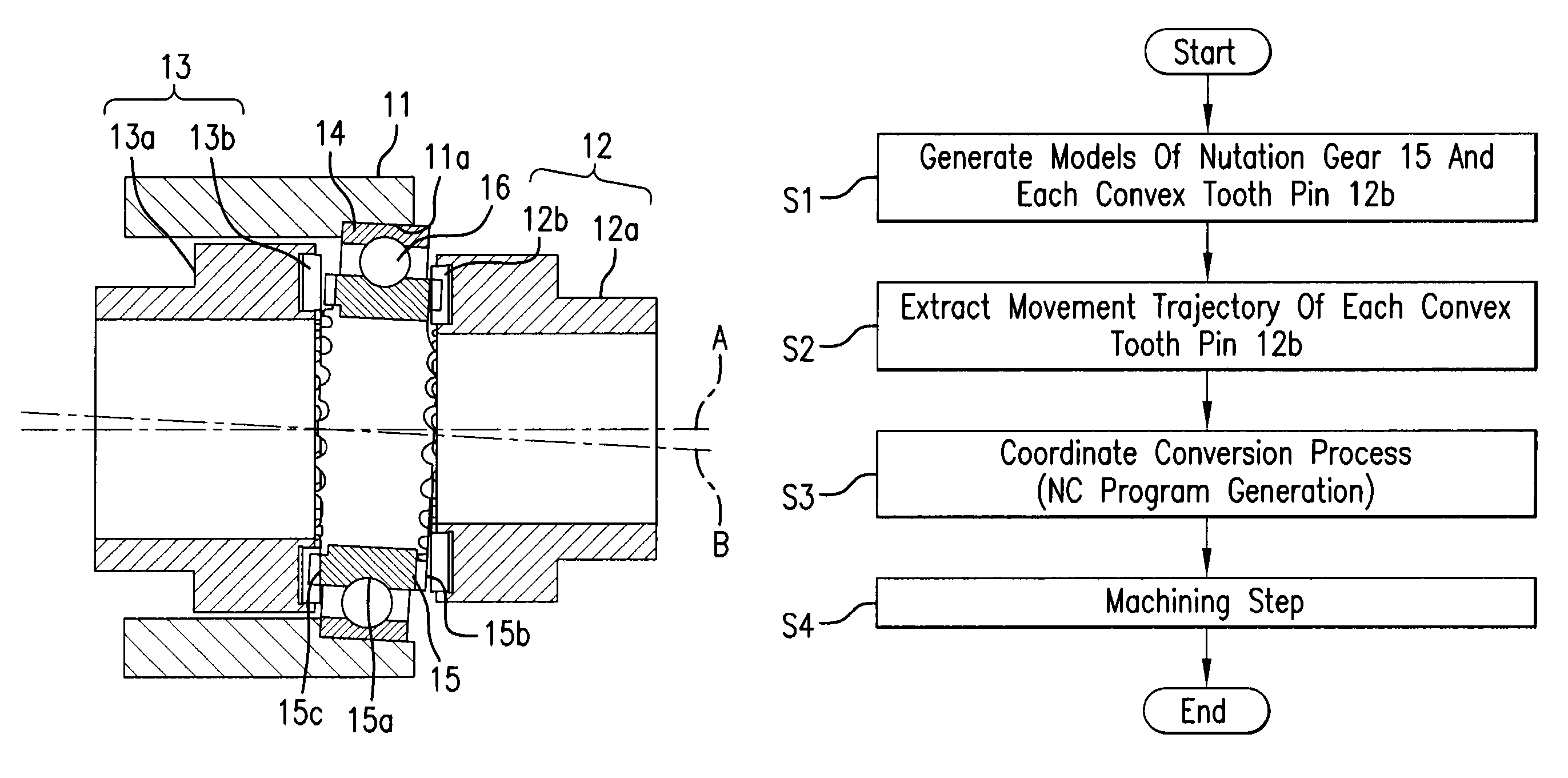
[0055]A machining method and machining device for a nutation gear of a nutation gear set according to a first embodiment will be described with reference to FIG. 1 to FIG. 9. The machining device in the present embodiment shows the case of a five-axis configuration having three orthogonal linear axes and two rotation axes. In the first embodiment, movement along a fourth rotation axis is decomposed into movement along a sixth indexing axis and movement along a third linear axis.

(1) Configuration of Nutation Gear Set

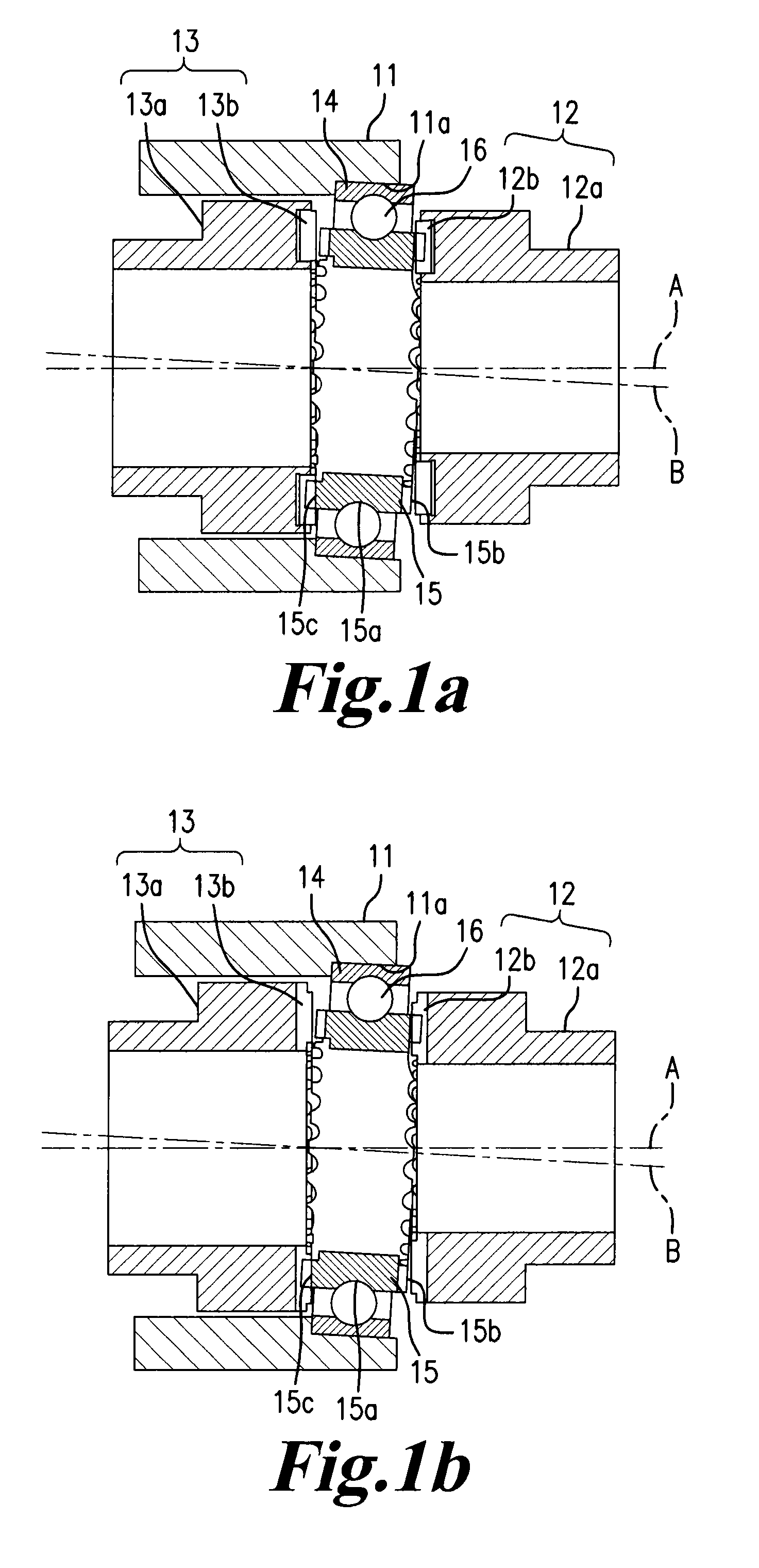
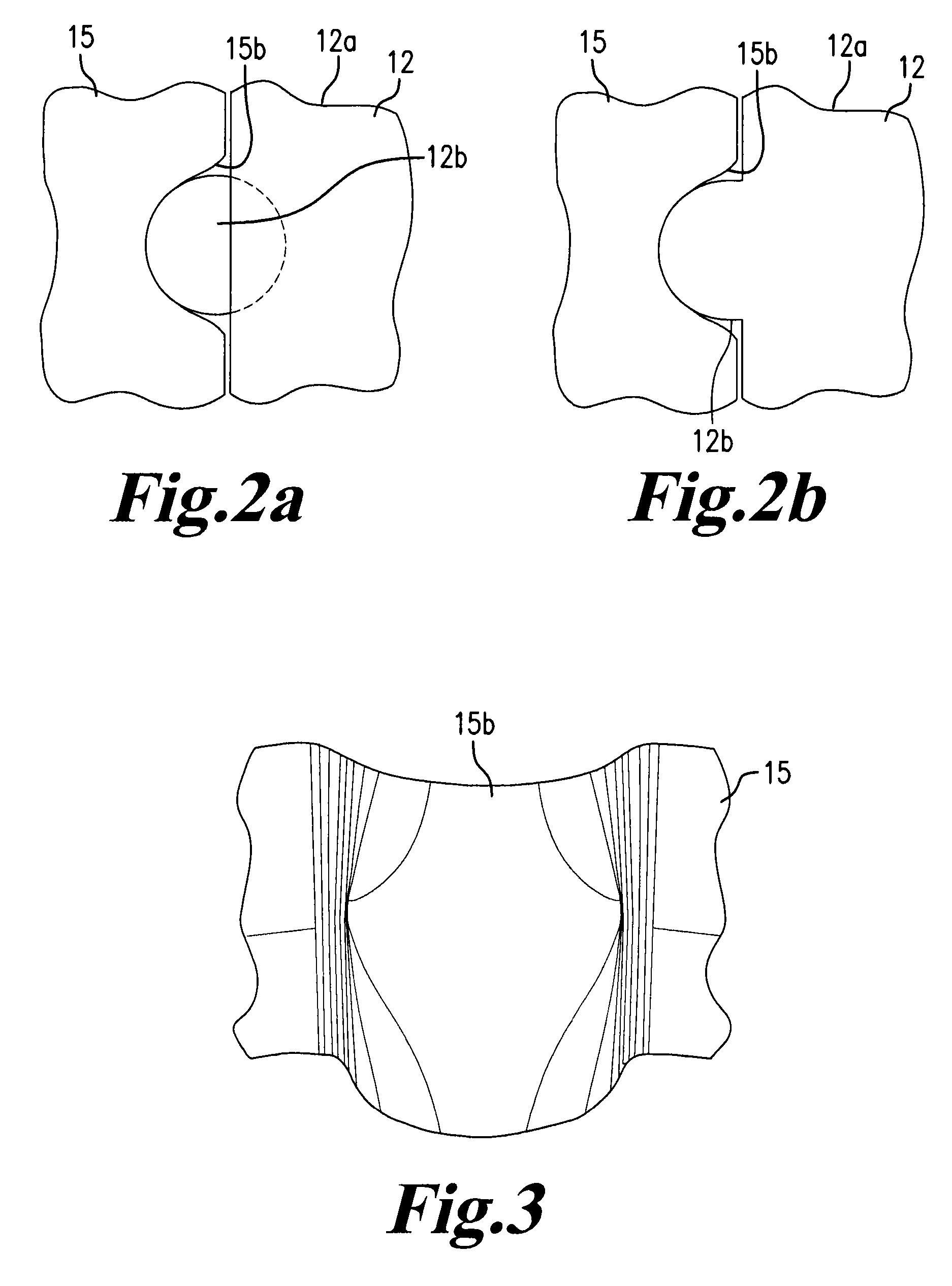
[0056]The configuration of the nutation gear set that uses the nutation gear that is a machining object of the invention will be described with reference to FIG. 1 to FIG. 4. Here, FIG. 1(a) shows a case where convex tooth pins 12b and 13b are respectively separately formed from a fixed shaft body 12a and an output shaft body 13a, and FIG. 1(b) shows a case...

second embodiment

Five-Axis Configuration (Three Linear Axes and Two Rotation Axes) (Second Example of Omission of Fourth Rotation Axis)

[0096]A machining method and machining device for a nutation gear of a nutation gear set according to a second embodiment will be described with reference to FIG. 12. The machining device in the present embodiment shows the case of a five-axis configuration having three orthogonal linear axes and two rotation axes. As in the case of the first embodiment, the fourth rotation axis is omitted. However, in the present embodiment, movement along the fourth rotation axis described in the first embodiment is decomposed not into movement along the sixth indexing axis and movement along the third linear axis but into movement along the sixth indexing axis and movement along the second linear axis.

[0097]Here, in the present embodiment, “model generation” (S1) and “trajectory extracting step” (S2) in the first embodiment are the same. That is, the movement trajectory of the con...

third embodiment

Four-Axis Configuration (Two Linear Axes and Two Rotation Axes) (Omission of Second Linear Axis and Fourth Rotation Axis)

[0102]A machining method and machining device for a nutation gear of a nutation gear set according to a third embodiment will be described with reference to FIG. 7, FIG. 8 and FIG. 13 to FIG. 15. The machining device in the present embodiment shows the case of a four-axis configuration having two orthogonal linear axes and two rotation axes. The fourth rotation axis and the second linear axis that are described in the first embodiment with reference to FIG. 7(a) and FIG. 7(b) are omitted. Specifically, as in the case of the first embodiment, movement along the fourth rotation axis is decomposed into movement along the sixth indexing axis and movement along the third linear axis, and, in addition, movement along the second linear axis is decomposed into the first linear axis and the third linear axis.

[0103]Here, in the present embodiment, “model generation” (S1) an...


PUM

PropertyMeasurementUnit
torqueaaaaaaaaaa
relative movement trajectoryaaaaaaaaaa
lengthaaaaaaaaaa

Abstract

A relative movement trajectory of each convex tooth pin of a mating gear with respect to a concave-convex gear at the time when torque is transmitted between the mating gear and the concave-convex gear (nutation gear) may be expressed by a first linear axis, a second linear axis, a third linear axis, a fourth rotation axis, a fifth rotation axis and a sixth indexing axis. Then, a relative movement trajectory of each convex tooth pin of the mating gear, expressed by the first linear axis, the second linear axis, the third linear axis, the fifth rotation axis and the sixth indexing axis in the case where the fourth rotation axis is brought into coincidence with the sixth indexing axis, is calculated, and at least one of a disc-shaped workpiece and a working tool is moved on the basis of the calculated relative movement trajectory.

Description

TECHNICAL FIELD[0001]The invention relates to a machining method for a concave-convex gear.BACKGROUND ART[0002]There is a nutation gear set as one of reduction gears. The nutation gear set is, for example, described in Patent Document 1, or the like. That is, the nutation gear set is formed of a first gear, a second gear and an input shaft that have the same rotation central axis, and a nutation gear that performs differential rotation with respect to the first gear and the second gear while wobbling therebetween. The nutation gear is supported by the input shaft so as to be rotatable about an inclined rotation central axis. Furthermore, the inclined rotation central axis relatively rotates about the rotation central axis of the first gear with the rotation of the input shaft. By so doing, the nutation gear wobbles with respect to the first gear and the second gear. Then, first nutation teeth that mesh with the first gear are formed on a face of the nutation gear, adjacent to the fi...

Claims


Application Information

Patent Timeline
Patent Type & Authority Patents(United States)
IPC IPC(8): B23F15/00
CPCB23F23/00B23F15/00F16H1/321Y10T409/10Y10T409/103975
Inventor ANDO, YOSHIAKITAKESHIMA, MASAYUKIHIROTA, IKUKO
Owner JTEKT CORP
Why Eureka
Try Eureka