
Air relief valve structure of pressure cooker

a pressure cooker and air relief valve technology, applied in the direction of functional valve types, baking vessels, containers, etc., can solve the problems of increasing the energy consumption, and increasing the price of some daily necessary materials. achieve the effect of easing pressure quickly

Inactive Publication Date: 2014-07-15
ZAO AN
View PDF1 Cites 66 Cited by
  • Summary
  • Abstract
  • Description
  • Claims
  • Application Information

AI Technical Summary

Benefits of technology

[0007]Therefore, it is a primary objective of the present invention to provide an air relief valve structure of a pressure cooker that allows food materials to be discharged from an air relief hole to prevent the food material from clogging the pressure cooker and reducing the relief pressure of the pressure cooker.
[0011]Another objective of the present invention is to discharge food debris quickly by an air relief hole with a greater diameter to achieve the effect of relieving pressure quickly.

Problems solved by technology

However, the oil price keeps increasing recently, and the price of some of the daily necessary materials also increases.
The longer the cooking time, the greater the energy consumption.
If the air relief hole is clogged by food materials, then, the purpose of relieving pressure cannot be achieved quickly and effectively.
The pressure relief valve fails to discharge gas quickly and effectively mainly due to the too-small air relief hole.
As a result, a small amount of food debris may occupy the whole pressure relief space easily and cause the failure of relieving the pressure.

Method used


Image

  • Air relief valve structure of pressure cooker
  • Air relief valve structure of pressure cooker
  • Air relief valve structure of pressure cooker

Examples


Embodiment Construction

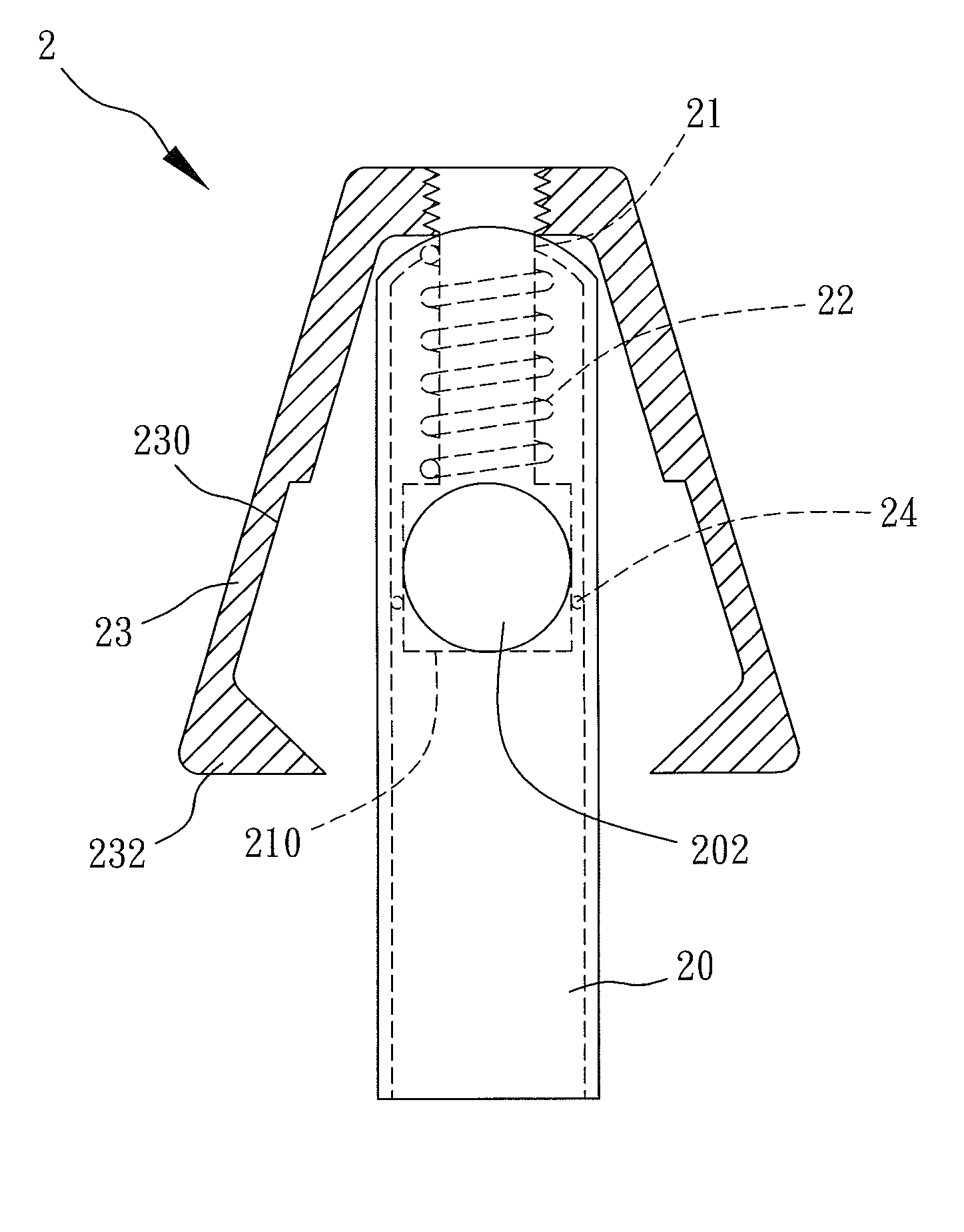
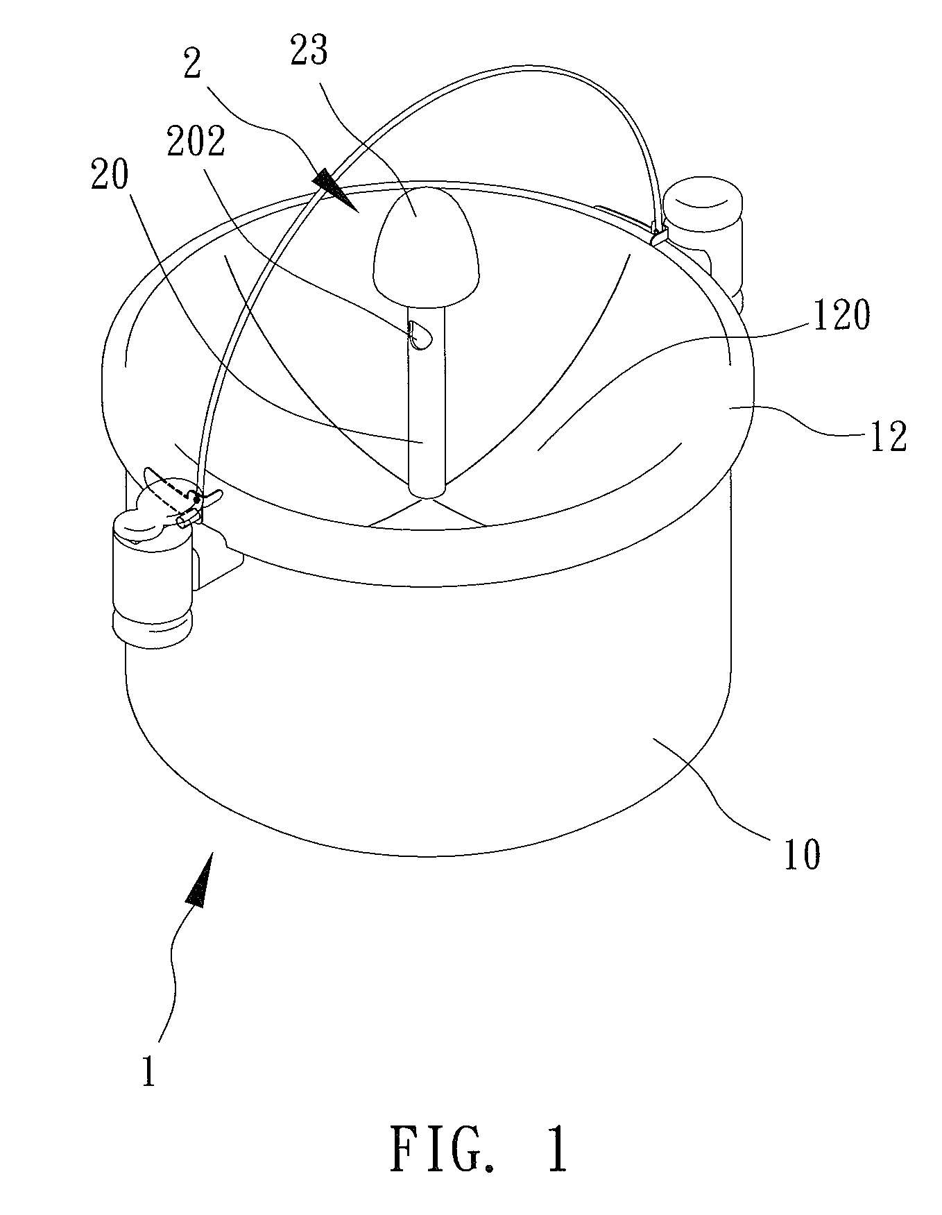
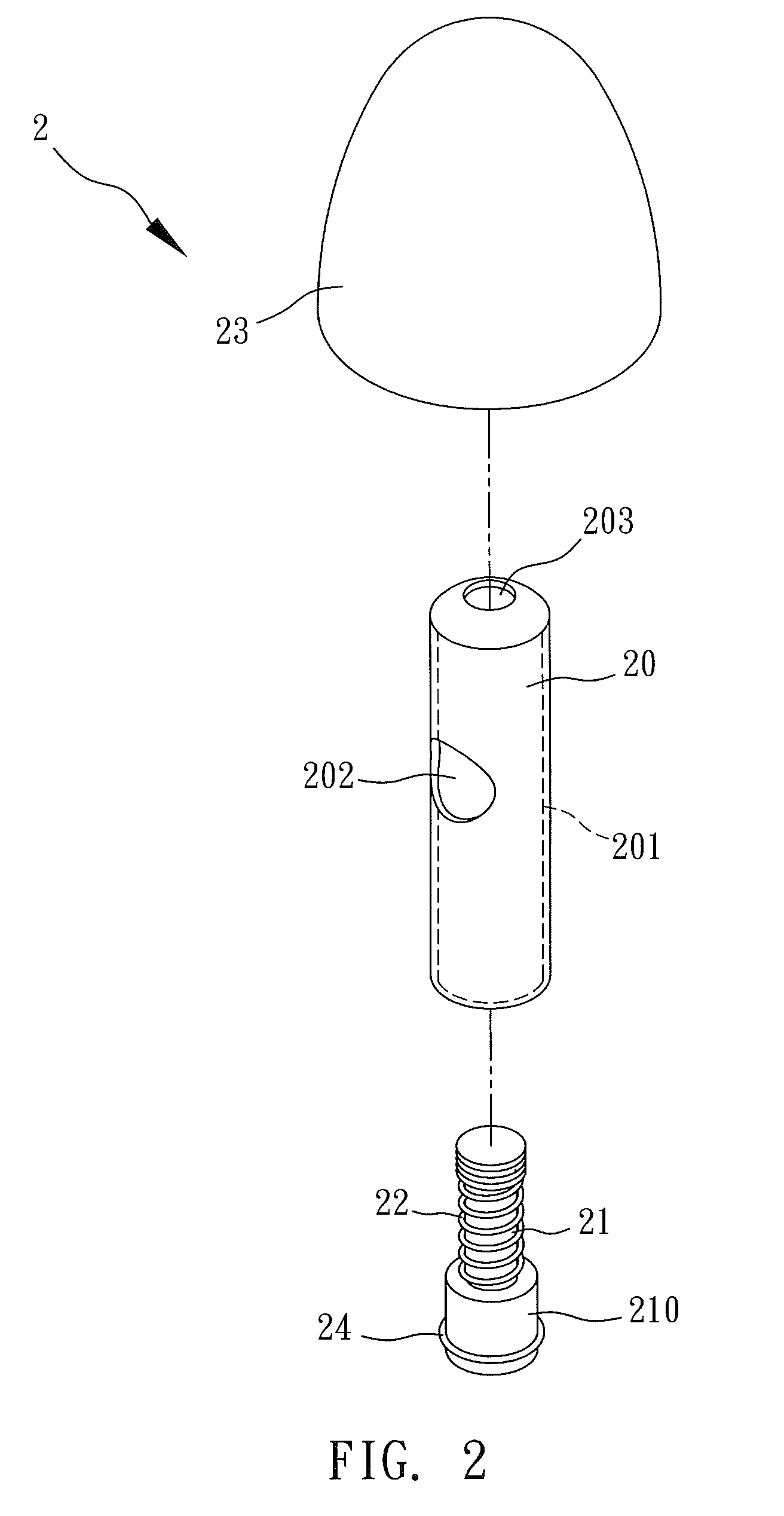
[0018]With reference to FIGS. 1 to 3 for an air relief valve structure of a pressure cooker in accordance with the present invention, the pressure cooker 1 comprises a cooker body 10 and a lid 12 covered onto the top of the cooker body 10. The lid 12 has a containing trough 120 formed therein, and an air relief valve 2 is installed at the containing trough 120. The air relief valve 2 includes a middle column 20 having a containing space 201 and at least one air relief hole 202 and a through hole 203 formed on an outer wall of the middle column 20 and interconnected with the containing space 201. An airtight column 21 is installed in the containing space 201, and has an end column 210 defined at an end of the airtight column 21 and disposed adjacent to an inner wall of the middle column 20 and the other end passing through the through hole 203. The end column 210 has a diameter equal to the diameter of the containing space 201 of the middle column 20. An elastic element 22 is sheathe...


PUM


Abstract

In an air relief valve structure of a pressure cooker, the pressure cooker includes a cooker body and a lid. The lid has a containing trough and an air relief valve. The air relief valve includes a middle column, an airtight column, an elastic element and a gravity valve. The middle column has a containing space and air relief and through holes formed on an outer wall of the middle column and interconnected with the containing space. In the containing space, an airtight column is installed. An end column is defined at an end of the airtight column and is disposed adjacent to an inner wall of the middle column, and the end column has a diameter equal to the diameter of the containing space of the middle column. The air relief hole allows food material to be discharged easily to reduce pressure and enhance the overall safety of the pressure cooker.

Description

BACKGROUND OF THE INVENTION[0001]1. Field of the Invention[0002]The present invention relates to an air relief valve and, in particular, to an air relief valve structure of a pressure cooker that allows food materials to be discharged from an air relief hole to prevent the food material from clogging the pressure cooker and reducing the relief pressure of the pressure cooker.[0003]2. Description of the Prior Art[0004]As civilization, science and technology advance, various modern products are introduced into our life. As to dining, people cooked rice and food by burning wood in the past, and started using products such as electronic cookers or electric cookers after electricity and gas are invented or discovered. However, some still use gas for cooking rice or other food. However, the oil price keeps increasing recently, and the price of some of the daily necessary materials also increases. Of course, these daily necessary materials also include the indispensable resources or energi...

Claims


Application Information

Patent Timeline
Patent Type & Authority Patents(United States)
IPC IPC(8): A47J27/092F16K17/36A47J27/09F16K17/38
CPCF16K17/36A47J27/092F16K17/38A47J27/09
Inventor WEN, CHIA-HENG
Owner ZAO AN
Learn More