
Axial flow fan

a technology of axial flow and fan blades, which is applied in the direction of liquid fuel engines, vessel construction, marine propulsion, etc., can solve the problem that the amount of dropping at the inflection point appearing in static pressure-air volume characteristics cannot be reduced with a conventional configuration, and achieve the effect of reducing the amount of dropping and reducing nois

Active Publication Date: 2014-07-08
SANYO DENKI CO LTD
View PDF11 Cites 3 Cited by
  • Summary
  • Abstract
  • Description
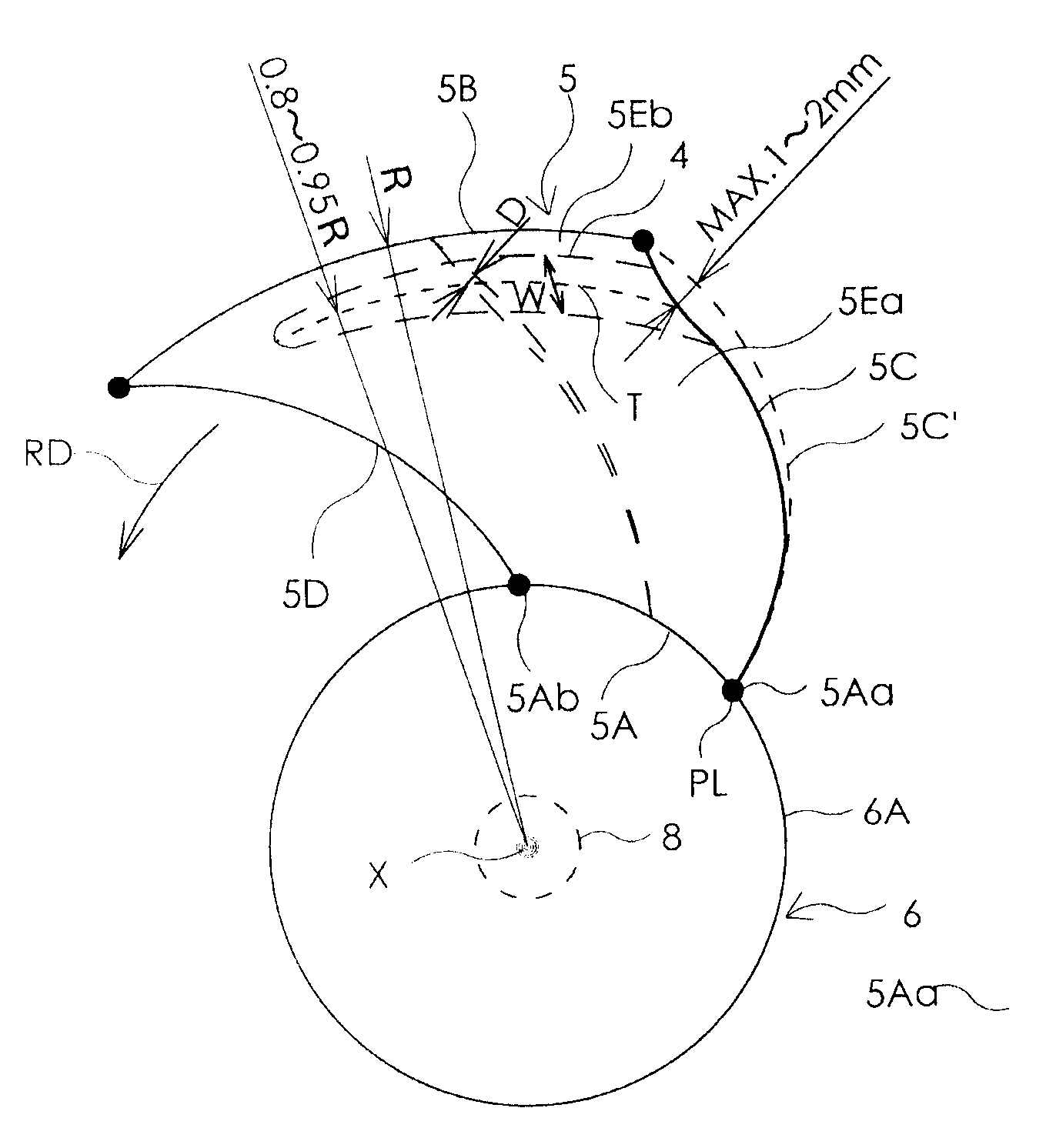
  • Claims
  • Application Information

AI Technical Summary

Benefits of technology

[0004]An object of the present invention is to provide an axial flow fan in which an amount of dropping at the inflection point appearing in air volume-static pressure characteristics may be reduced and noise may also be reduced as compared to conventional axial flow fans.
[0007]With the above configuration, it is possible to reduce the amount of dropping at the inflection point appearing in air volume-static pressure characteristics and reduce noise as compared to a conventional axial flow fan in which a projecting edge is formed over the entire length of the radially outer end portion of the blade. The effects obtained in the present invention were confirmed by experiments.
[0008]It is preferable that the shape of the blade be determined such that outer surface portions positioned on both sides of the curved portion in the radial direction exist in the same curved surface. In other words, it is preferable that one outer surface portion positioned on one side of the curved portion exist on an extended surface of the other outer surface portion positioned on the other side of the curved portion. By defining the shape of the curved portion in this manner, it is possible to increase the inflection point appearing in air volume-static pressure characteristics and reduce noise as compared to the conventional axial flow fan in which a projecting edge is formed.
[0009]It is preferable that, as the impeller is viewed from the front end portion of the rotary shaft toward the rear end portion thereof, an outline of the rear end edge of the blade be curved to be convex in the rotation direction at a position corresponding to the curved portion. By defining the shape in this manner, it is possible to reduce the amount of dropping at the inflection point appearing in air volume-static pressure characteristics and reduce noise.
[0014]According to the present invention, it is possible to reduce the amount of dropping at the inflection point appearing in air volume-static pressure characteristics than in a conventional axial flow fan in which a projecting edge is formed over the entire length of the radially outer end portion of the blade, which further leads to a reduction in noise.

Problems solved by technology

However, from the practical point of view, the amount of dropping at the inflection point appearing in static pressure-air volume characteristics cannot be reduced with a conventional configuration.

Method used


Image

  • Axial flow fan
  • Axial flow fan
  • Axial flow fan

Examples


Embodiment Construction

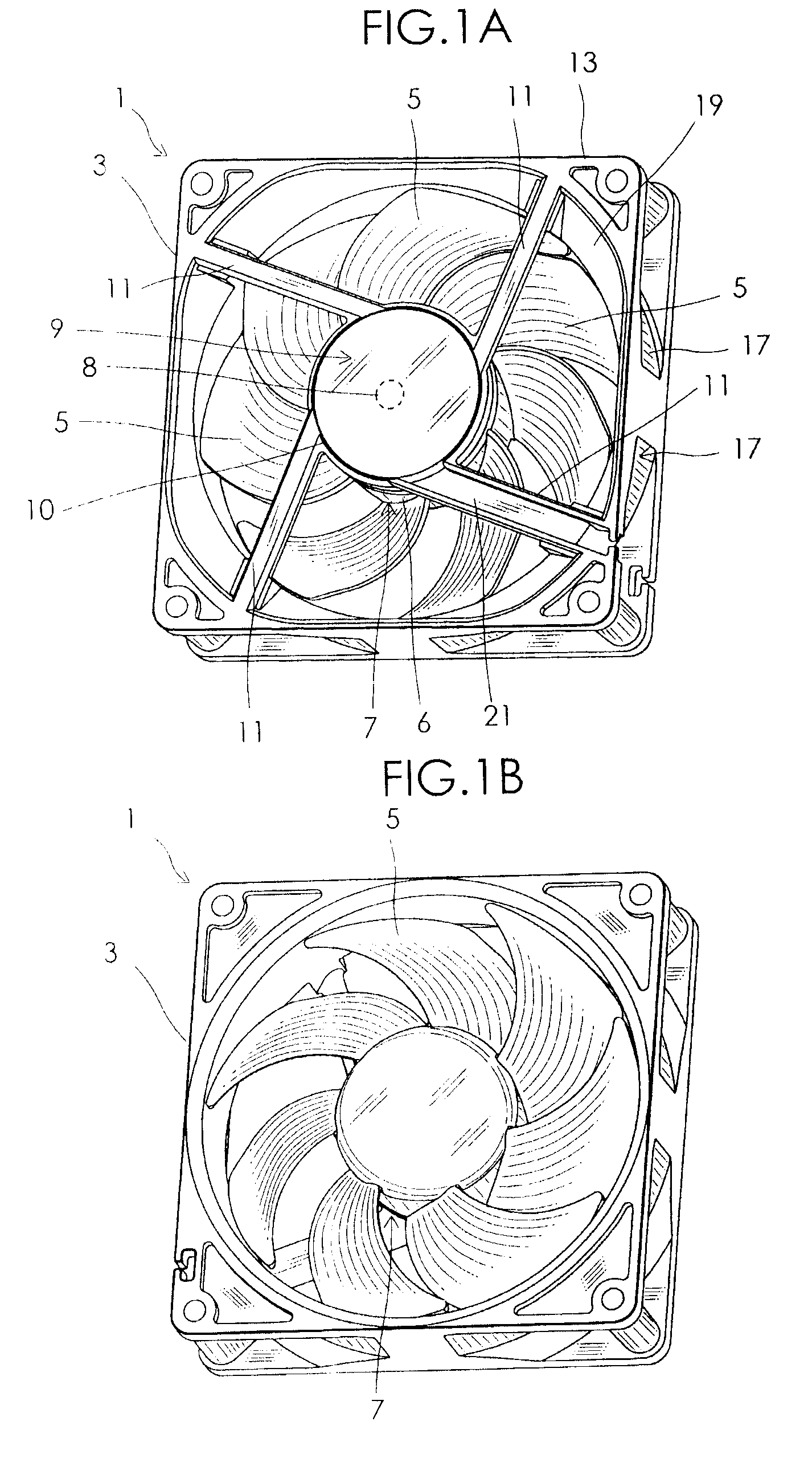
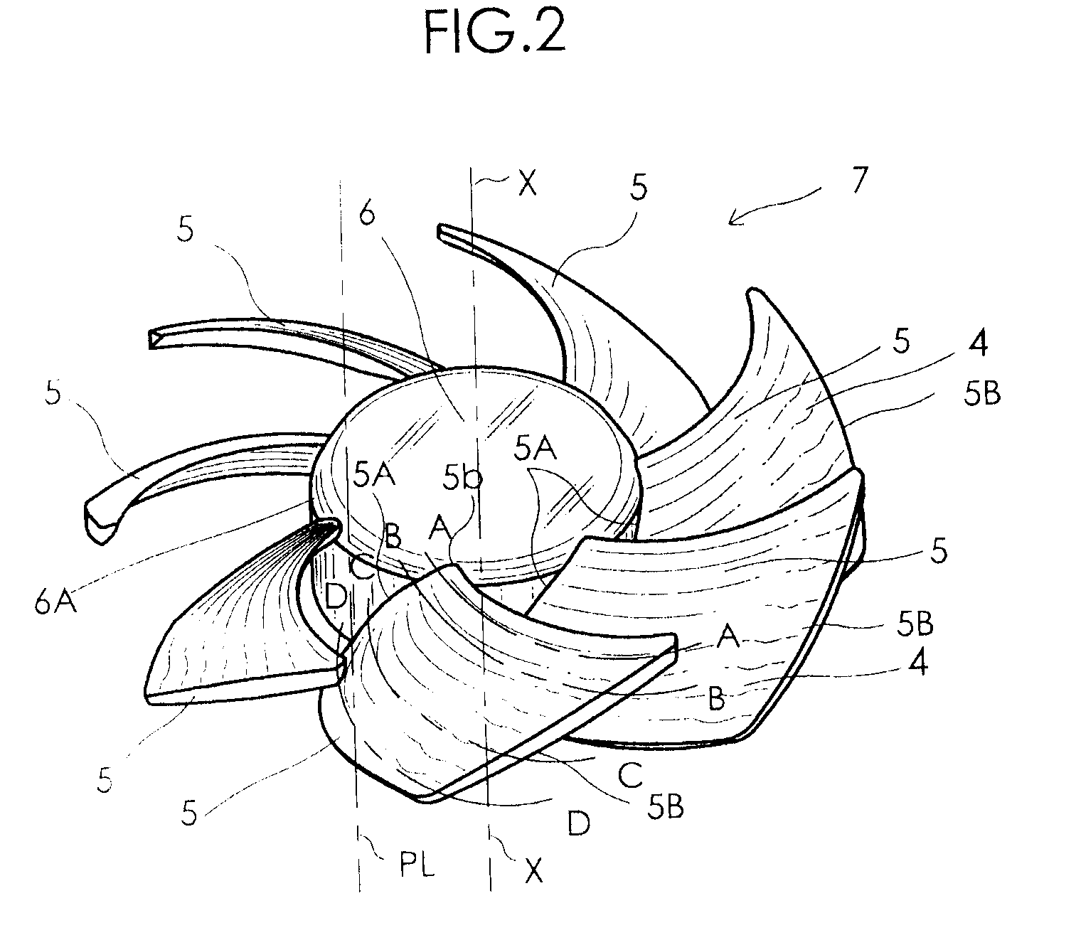
[0027]An embodiment of an axial flow fan according to the present invention will be described in detail hereinbelow with reference to the accompanying drawings. FIGS. 1A and 1B are respectively a front-side perspective view and a rear-side perspective view of an axial flow fan 1 according to an embodiment of the present invention. The axial flow fan 1 includes a housing 3, an impeller 7 having seven blades 5 which are disposed in the housing 3 and rotating therein, and a motor 9 which drives and rotates the impeller 7. The motor 9 includes a rotary shaft 8, as indicated with a dot line, having a front end portion and a rear end portion. The impeller 7 is fixed to the front end portion of the rotary shaft 8. A motor case 10 is fixed to the housing 3 through webs 11. The housing 3 has a suction-side flange 13 of an annular shape at one side in an extending direction of the axial line (axial direction) of the rotary shaft 8 and a discharge-side flange 15 of an annular shape at the othe...


PUM


Abstract

An axial flow fan includes a blade having a curved portion formed in the vicinity of a radially outer end portion positioned opposite to the base portion in the radial direction of the peripheral wall portion of the hub. The curved portion is convex in the rotation direction, concave in the direction opposite to the rotation direction, and extends along the radially outer end portion of the blade. The curved portion extends from a rear end edge of the blade, positioned on a side where one end of the base portion of the blade is positioned, and extends in the radial direction of the hub to the vicinity of a front end edge of the blade, positioned on a side where the other end of the base portion of the blade is positioned and extending in the radial direction.

Description

TECHNICAL FIELD[0001]The present invention relates to an axial flow fan.BACKGROUND ART[0002]Japanese Utility Model Registration No. 3089140 (U.S. Patent Application Publication No. 2003 / 0123988) discloses in FIGS. 1 to 3 an impeller of an axial flow fan in which a projecting edge 322 curved to form an included angle θ on the upper surface of a blade 32 is formed at a radially outer end portion thereof.[0003]Japanese Utility Model Registration No. 3089140 (U.S. Patent Application Publication No. 2003 / 0123988) describes that vortices 23 are generated at the radially end portion 13 of the blade as shown in FIG. 5 of the publication if the projecting edge 322 is not formed. Further, the publication describes that the vortex 23 leads to a reduction of static pressure, reduction of air volume, and increase of noise. Furthermore, the publication describes that the formation of the projecting edge 322 allows the static pressure to be increased, air volume to be increased, and noise to be re...

Claims


Application Information

Patent Timeline
Patent Type & Authority Patents(United States)
IPC IPC(8): F01D1/04F01D5/16F01D5/14
CPCF04D29/384F05D2240/307F04D25/0613
Inventor ISHIHARA, KATSUMICHI
Owner SANYO DENKI CO LTD
Learn More