
Method and device for weight precise cutting of a food strand

a technology of food strands and precision cutting, which is applied in the direction of meat processing, meat shaping/cutting, fish processing, etc., can solve the problems of preventing a reliable detection of pattern, affecting the accuracy of food strands, and affecting the quality of food strands,

Active Publication Date: 2014-06-24
REIFENHAEUSER UWE
View PDF15 Cites 15 Cited by
  • Summary
  • Abstract
  • Description
  • Claims
  • Application Information

AI Technical Summary

Benefits of technology

[0031]Through the method according to the invention the object can be achieved in a particularly advantageous manner in that the additional fourth detector facilitates detecting also portions which are not detectable by the other three known detectors since the additional fourth detector is arranged on “another” side of the marking compared to the other three detectors.
[0035]This has the effect that even edge portions can be precisely measured and can be cut by the cutting device with high precision. Wasted cutting material due to imprecise detection of edge portions with complicated shapes can therefore be omitted, wherein the food strand can be utilized to a higher percentage compared to known techniques.
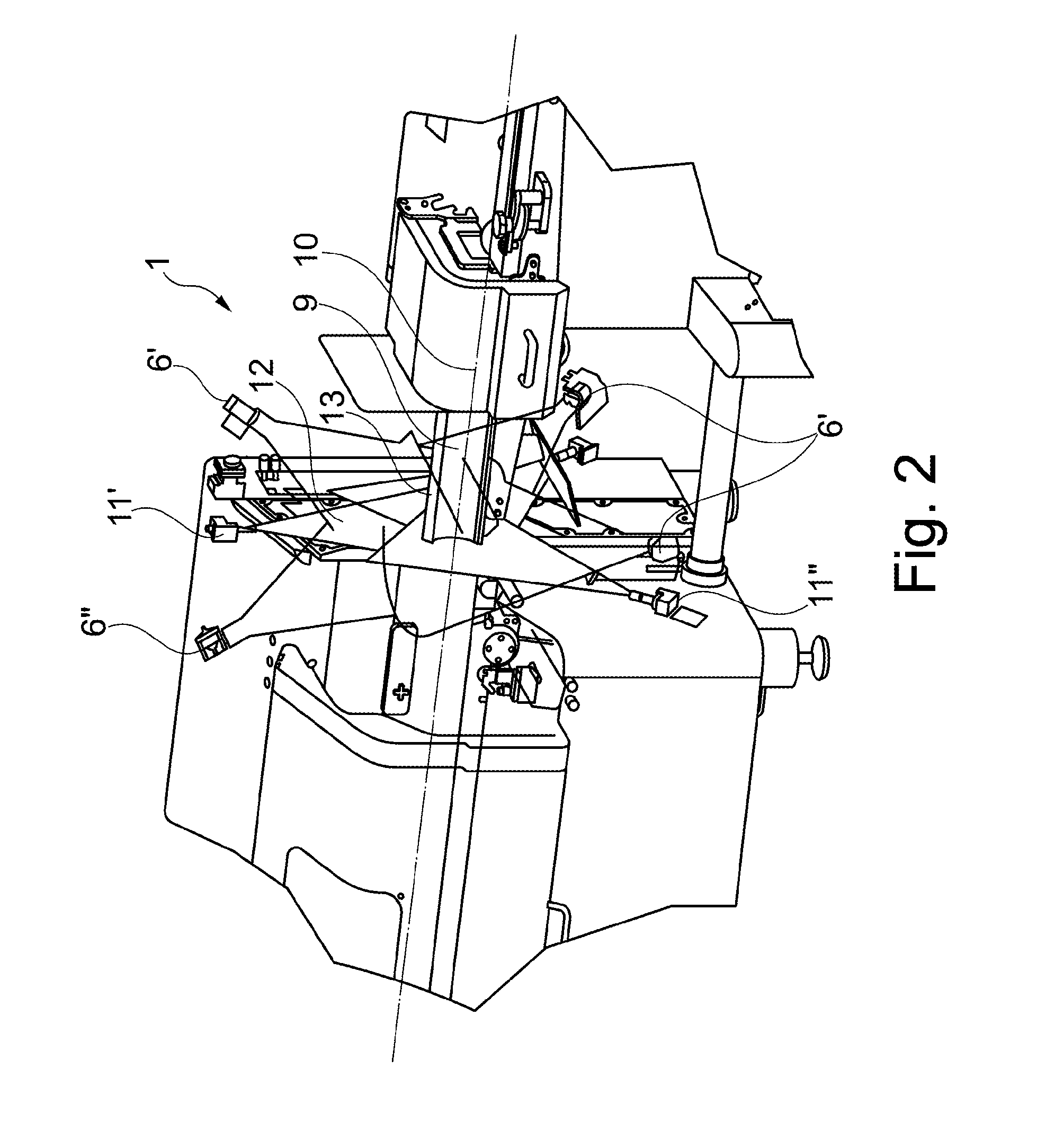
[0043]It is furthermore advantageous when an optical axis of at least one detector, preferably of two detectors arranged below the food strand enclose an angle between 5° and 50°, preferably between 10° and 30° with a plane that includes the marking and that is orthogonal to the feed direction of the food strand.

Problems solved by technology

The known system, however, has a weakness when measuring end pieces and irregular surface contours, in particular including cavities extending into the food strand at a slant angle.
In this case shadowing occurs in particular for irregular convex cambered end pieces and cavities with small curvature radii which prevent a reliable detection of the pattern generated by the lasers through the cameras.
This application relates in particular to the problem that a reliable determination of the edge contour or of the surface of the food strand is not easily possible in cases in which the food strand has a highly irregular structure as can be the case of strands of pork chops.
Irregularities cause in particular the problem of shadowing particular portions as soon as the light emitted by the light emitter cannot reach every location of the cross section any more due to the irregular shape of the food strand so that the edge contour consequently “disappears” in these portions.
Measuring errors and lack of precision of the masses of the particular slices come as a consequence.
Though this device provides sufficient precision for some applications with respect to mass deviations of the particular slices of the food strand a safe prevention of shadowing of the edge contour which makes the edge contour invisible and not monitorable by the cameras cannot be safely provided by this device in all cases.
The results of the measurement from the bottom side are flawed accordingly since the marking on the food strand is incomplete due to the plurality of support rods so that interpolation processes are required for the shadowed portions, which has a negative effect on precision.
However, the known projector and camera technique and arrangement is not suitable for a method in which the measurement and evaluation of the measurement data obtained has to be continuously performed with uninterrupted feeding in order to be able to determine and adjust the required slice thickness in time before reaching the cutting plane.

Method used


Image

  • Method and device for weight precise cutting of a food strand
  • Method and device for weight precise cutting of a food strand
  • Method and device for weight precise cutting of a food strand

Examples


Embodiment Construction

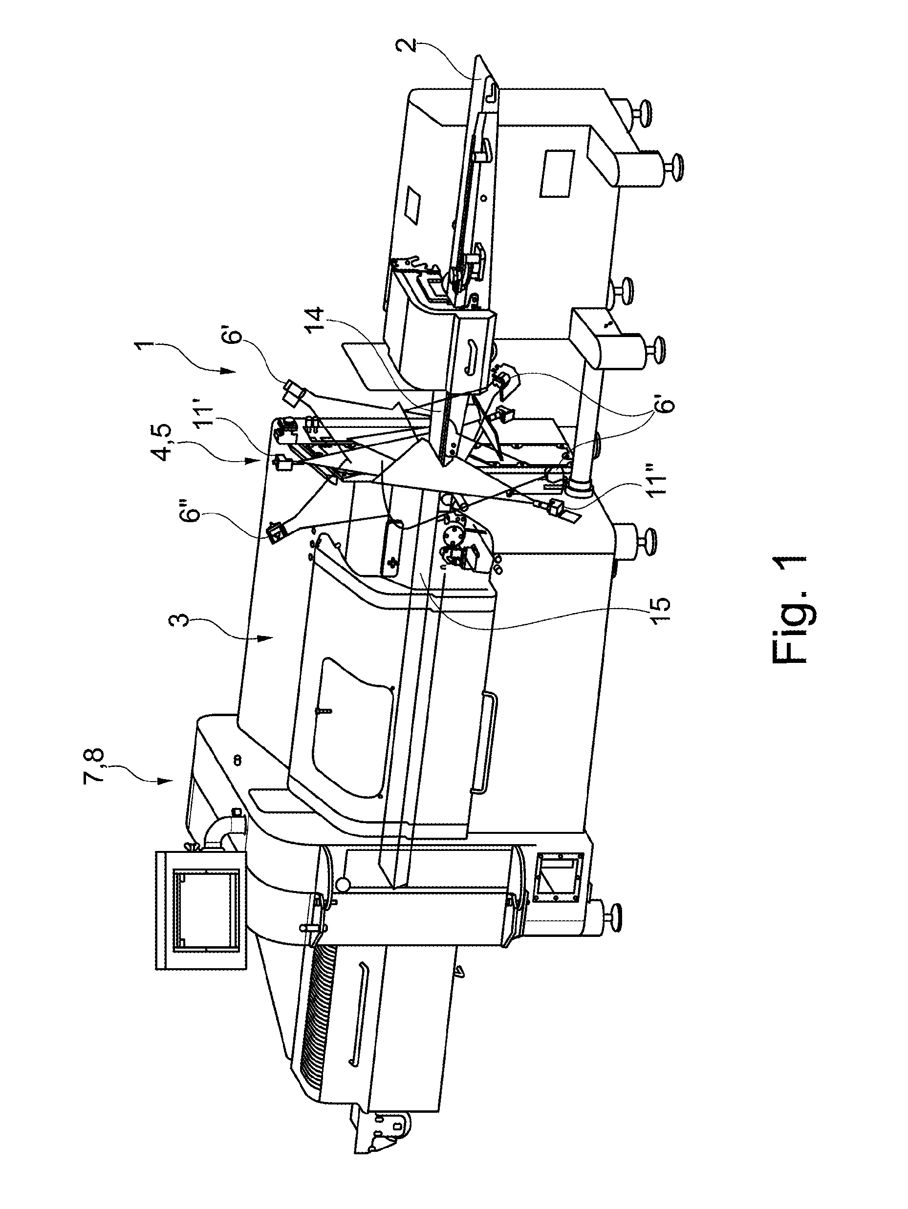
[0051]The embodiment illustrated in FIGS. 1-6 illustrates a device 1 according to the invention for weight precise cutting including a feed device 2, cutting device 3 and a measuring device 4, wherein the measuring device 4 includes a marking device 5, four detectors 6′, 6″ and a processing device 7. The device 1 furthermore includes a control device 8 through which the feed device 2 is controlled as a function of the configuration of a food strand 9.

[0052]The feed device 2 is configured to feed the food strand 9 towards the cutting device 3, wherein the longitudinal axis 10 of the food strand 9 is oriented parallel to the feed direction of the feed device 2. Thus, the feed device 2 is typically configured as a conveyor belt, wherein the conveyor belt includes a plurality of conveyor belt elements arranged in series and adjacent to the transition gaps or at least close to the transition gaps.

[0053]Before the food strand 9 reaches the cutting device 3 it is measured through the measu...


PUM


Abstract

A method for cutting a food strand into portions including the steps:feeding the food strand through a feed device towards a cutting device;continuously measuring a cross section of the food strand during feeding with a measuring device;continuously generating a marking on a surface of the food strand through a marking device;continuously detecting the marking through three first detectors arranged on identical sides of the marking with respect to the feed direction;continuously determining a size of a cross sectional surface of the food strand through a processing device from image data generated by the first detectors and a fourth detector;controlling the cutting device and / or the feed device through a control device using data of the size of the cross sectional surface; andcontinuously detecting the marking through a fourth detector arranged on another side of the marking than the three first detectors.

Description

RELATED APPLICATIONS[0001]This application claims priority from German application DE 10 2012 102 649.1 filed on Mar. 27, 2012, which is incorporated in its entirety by this reference.FIELD OF THE INVENTION[0002]The invention relates to a method for cutting at least one food strand into portions with precise weights.BACKGROUND OF THE INVENTION[0003]A method and a device of the general type described supra is for example known from GB 2 377 362 A. They are essential in particular for the so called weight precise cutting since food strands with irregular shapes, typically naturally grown food strands, for example pork chop strands are typically cut into individual slices which shall have uniform masses. The requirement to produce identical package weights for the sale of the products is of interest for example in self service sections of super markets.[0004]In the method disclosed in GB 2 377 362 A, a marking is generated on a surface of the food strand to be cut through four lasers r...

Claims


Application Information

Patent Timeline
Patent Type & Authority Patents(United States)
IPC IPC(8): A22C18/00
CPCB26D5/007B26D7/0683B26D5/34B26D7/0625B26D2210/02A22C17/002B26D7/30
Inventor REIFENHAEUSER, UWE
Owner REIFENHAEUSER UWE
Learn More