Apparatus for producing X-rays for use in imaging

a technology for producing apparatus and x-rays, applied in the direction of x-ray tube electrodes, electrical apparatus, electric discharge tubes, etc., can solve the problems of affecting the x-ray output, so as to improve the x-ray output, the effect of doubling the gap field and optimizing the response of the crystal

Active Publication Date: 2014-06-17
RGT UNIV OF CALIFORNIA
View PDF27 Cites 11 Cited by
  • Summary
  • Abstract
  • Description
  • Claims
  • Application Information

AI Technical Summary

Benefits of technology

[0020]One advantage realized with a piezoelectric based embodiment is that it can be excited by acoustic means including transducers and mechanical actuators. In addition, it may be possible to induce the piezoelectric spontaneous polarization using a shock wave produced through a laser pulse, for example. In addition to a possibly more practical production method, the piezoelectric approach might allow for faster time scale control.
[0044]An aspect of the invention is to provide an x-ray or electron source that is portable, easy to use and that does not require a large outside power source to function.

Problems solved by technology

Conventional tubes can be relatively light (a few kilograms) and fragile, since they are fabricated from glass.
However, the power supplies are typically large, expensive and heavy (in the tens of kilograms).
The majority of the applied power goes into waste heat, requiring cooling and further adding to the bulk and weight of conventional x-ray devices.
These devices still require external high voltage supplies (as well as water cooling, in some cases); however, the weight of the unit itself (excluding the power supply and cooling system) is very low.
As they are typically designed for cancer therapy, where dose precision is critical, the designs are not optimized for cost.
Maintaining a sufficiently high voltage (30-120 kV) across a tiny gap without breakdown is very challenging and has been a barrier to miniaturization.
This approach seems very promising, but still requires a significant external power supply.
However, concerns about safety and nuclear material proliferation make these systems very undesirable.
Moreover, shielding of the sources implies that devices tend to be very heavy on the order of hundreds of kilograms.
However, it lacks repeatability or control and also has a nearly random output flux.

Method used


Image

  • Apparatus for producing X-rays for use in imaging
  • Apparatus for producing X-rays for use in imaging
  • Apparatus for producing X-rays for use in imaging

Examples


example 1

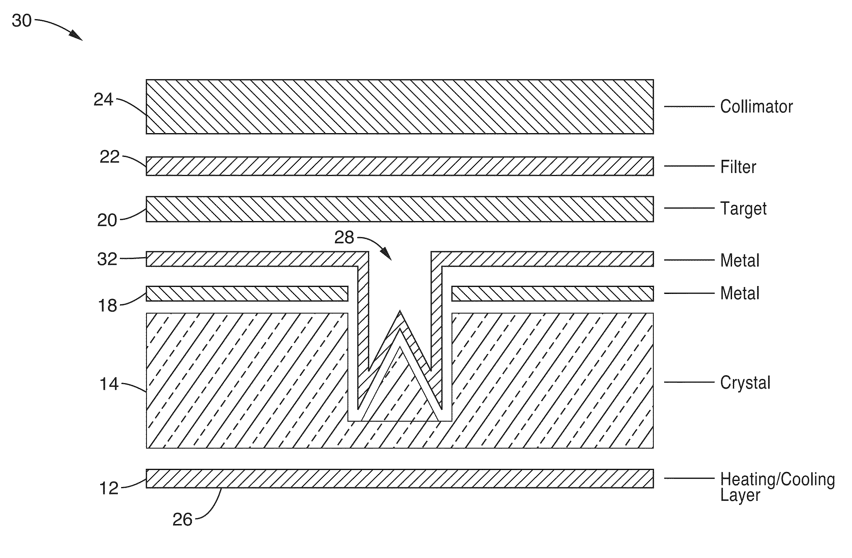
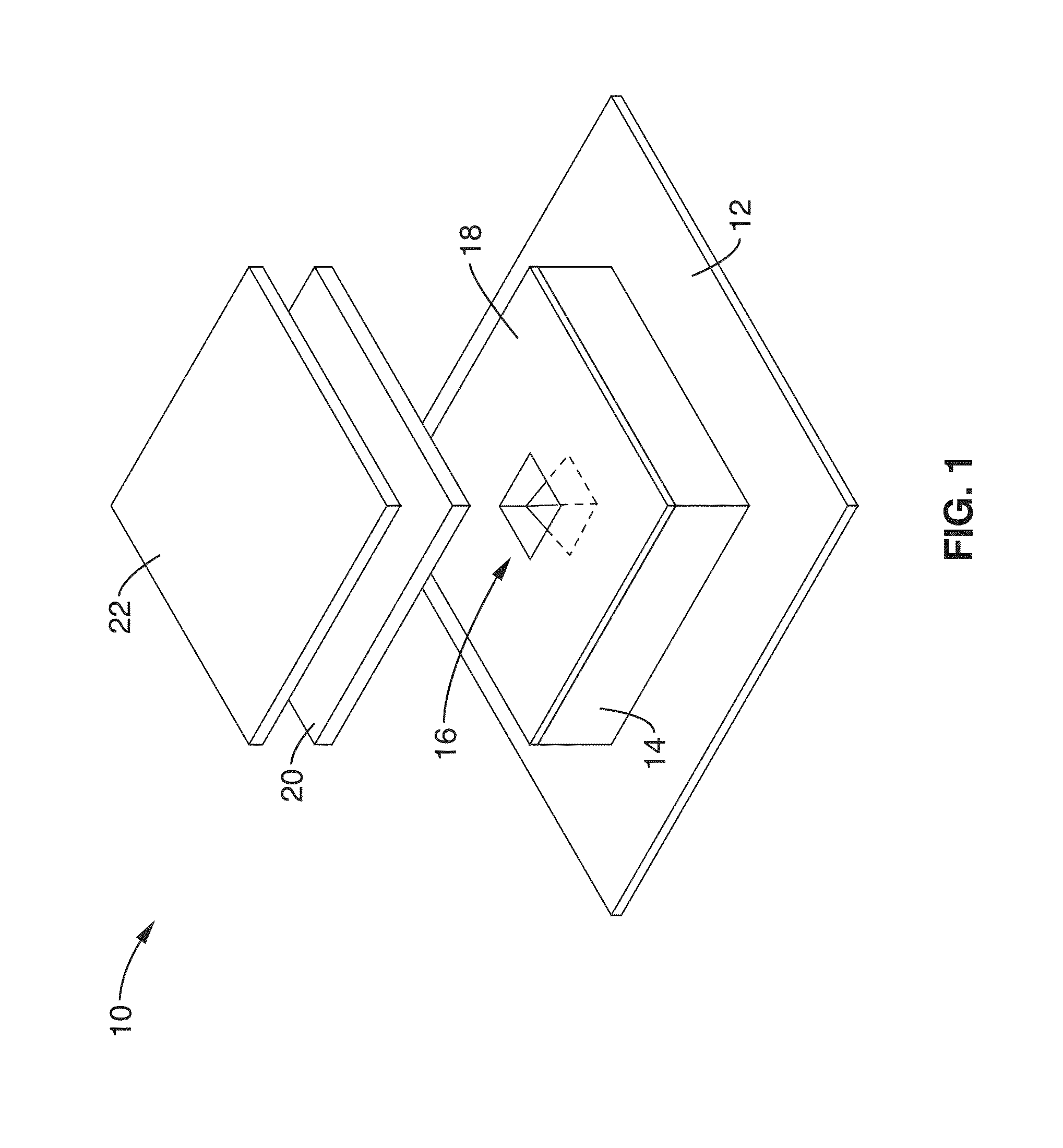
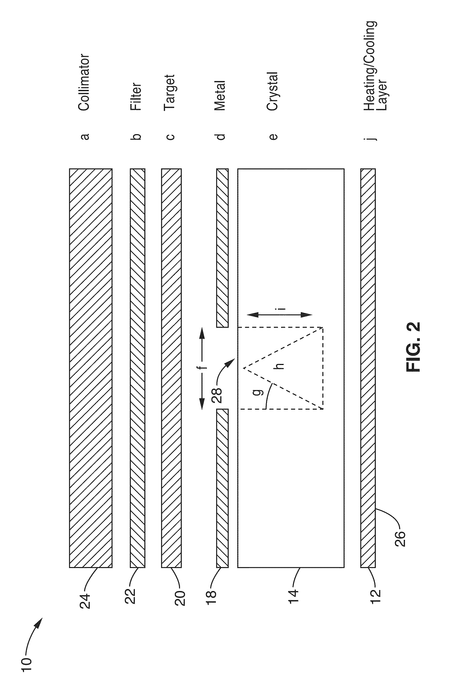
[0117]In order to demonstrate the functionality of the apparatus, pyroelectric crystals with a variety of field emission tip configurations according to the invention were produced and evaluated. Previous experimental findings on pyroelectric electron emission from lithium niobate (LiNbO3) crystals have demonstrated that both qualitative and quantitative features of the emission are strongly dependent on the detailed geometry of the experiment, including the vacuum vessel, anode configuration, and crystal size and shape. Depending on the ambient gas pressure, rate of temperature change, and anode distance, currents can be produced through field emission, surface plasma formation, or gas ionization; currents of picoamperes to nanoamperes have been reported, over time scales of a few minutes to a few hours. Therefore, lithium niobate (LiNbO3) crystals are a good illustration of one apparatus for x-ray production according to the invention.

[0118]A first series of experimental tests was...


PUM


Abstract

An apparatus for producing x-rays for use in imaging applications having a piezoelectric or pyroelectric crystal with an upper surface and a conducting film coating the upper surface. The crystal includes a plurality of field emitters formed as micrometer-scale exposed regions in the crystal having a one or more sharp peaks or ridges, or parallel trenches forming a wedge shaped emitter. The crystal is alternately heated and cooled over a period of time so that spontaneous charge polarization occurs in the crystal. The spontaneous charge polarization causes a perpendicular electric field to arise on the crystal's top and bottom faces, that is enhanced by the sharp peaks or ridges, thereby causing field emission of surface electrons from that location. X-rays are produced when the emitted electrons strike a target material located adjacent to the emitting face, and the X-rays may be filtered or collimated.

Description

CROSS-REFERENCE TO RELATED APPLICATIONS[0001]This application a 35 U.S.C. §111(a) continuation of PCT international application number PCT / US2010 / 044762 filed on Aug. 6, 2010, incorporated herein by reference in its entirety, which is a nonprovisional of U.S. provisional patent application Ser. No. 61 / 232,317 filed on Aug. 7, 2009, incorporated herein by reference in its entirety. Priority is claimed to each of the foregoing applications.[0002]The above-referenced PCT international application was published as PCT International Publication No. WO 2011 / 017645 on Feb. 10, 2011 and republished on Jun. 9, 2011, and is incorporated herein by reference in its entirety.STATEMENT REGARDING FEDERALLY SPONSORED RESEARCH OR DEVELOPMENT[0003]This invention was made with Government support under Grant No. HDTRA1-09-1-0043 awarded by United States Defense Threat Reduction Agency (DTRA). The Government has certain rights in this invention.INCORPORATION-BY-REFERENCE OF MATERIAL SUBMITTED ON A COMPA...

Claims


Application Information

Patent Timeline
Patent Type & Authority Patents(United States)
IPC IPC(8): H01J35/00H01J35/06
CPCH01J35/065
Inventor TRAVISH, GILYODER, RODNEYROSENZWEIG, JAMES
Owner RGT UNIV OF CALIFORNIA
Why Eureka
Try Eureka