
Tandem differential mobility ion mobility spectrometer for chemical vapor detection

a spectrometer and ion mobility technology, applied in the field of chemical sensing systems, can solve the problems of looming possibility that civilians and first responders may be exposed to environments involving hazardous chemicals including cwas, no portable sensor technology exists, and both tof-ims and dms are increasingly subject to false detection, so as to reduce false detections, reduce false detections, and improve performan

Active Publication Date: 2014-06-17
HAMILTON SUNDSTRAND CORP
View PDF21 Cites 7 Cited by
  • Summary
  • Abstract
  • Description
  • Claims
  • Application Information

AI Technical Summary

Benefits of technology

[0008]The combination of the differential mobility of the DMS and ion mobility of the IMS provides significant resolving power. The physical-chemical principles upon which the resolving properties of these devices are based differ sufficiently that their ion separations are highly orthogonal. Under this condition, the effective resolving power of the detection system approximates the product of the resolving power of each system alone. This allows the system to detect chemicals in air at ultra-trace levels while minimizing false positive detections. Moreover, the tandem sensor technologies upon which this higher performance is based are still particularly well suited to miniaturization, low power implementation and relatively low manufacturing cost.

Problems solved by technology

There is a looming possibility that civilians and first responders may be exposed to environments involving hazardous chemicals including CWAs.
No portable sensor technology exists that can detect specified lists of TICs and CWAs at the sub-ppb levels in real time and with acceptable false-alarm rates in the presence of common environmental chemical backgrounds.
However, both TOF-IMS and DMS are increasingly subject to false detection as sensor gain is increased and sub-ppm limits of detection are pursued, this due to the more complex nature of samples at ppb and ppt levels.
While DMS technology has the sensitivity to approach PEL level detection of CWAs without preconcentration, resolution becomes a limiting factor in the presence of trace environmental chemical backgrounds.

Method used


Image

  • Tandem differential mobility ion mobility spectrometer for chemical vapor detection
  • Tandem differential mobility ion mobility spectrometer for chemical vapor detection
  • Tandem differential mobility ion mobility spectrometer for chemical vapor detection

Examples


Embodiment Construction

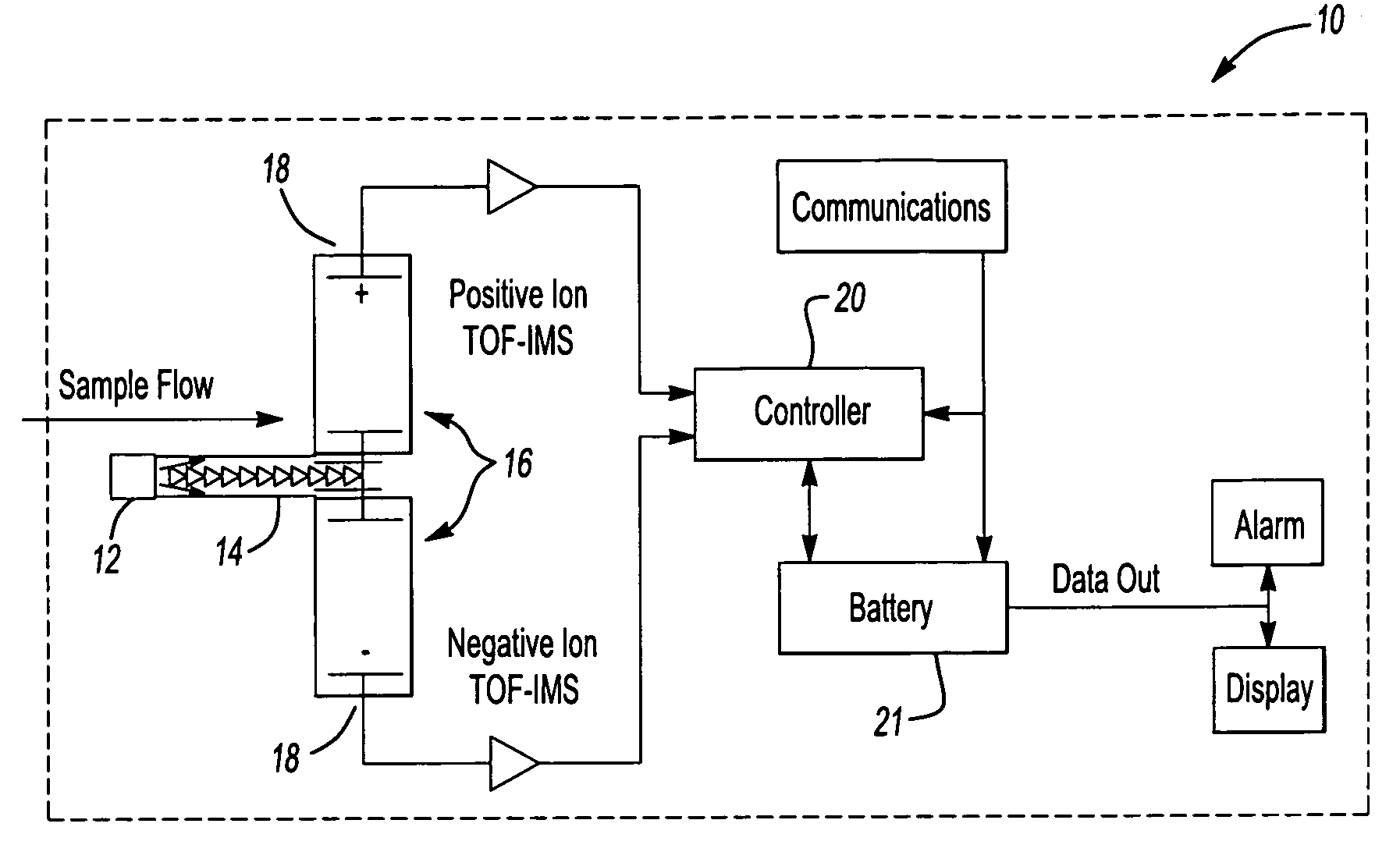
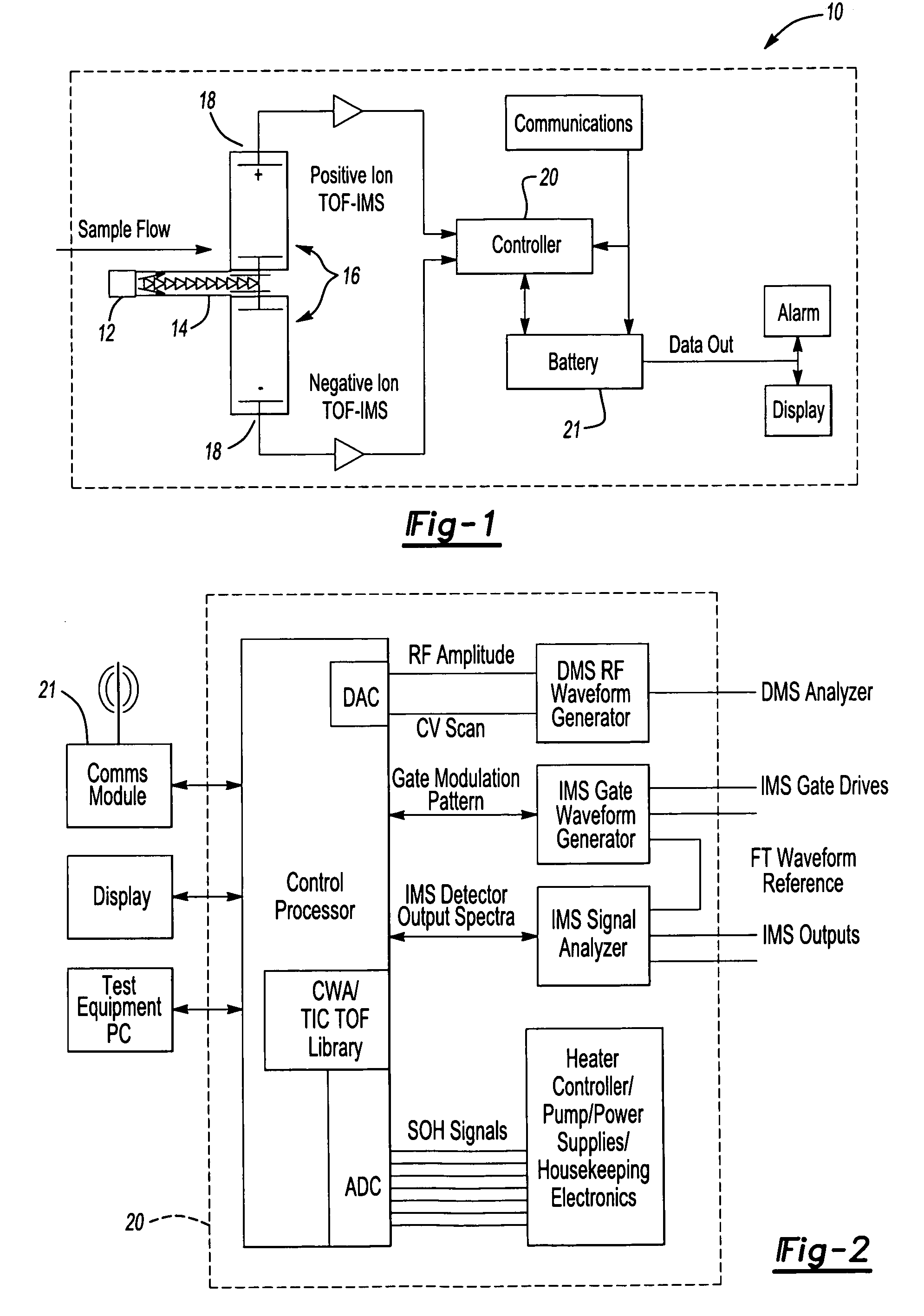
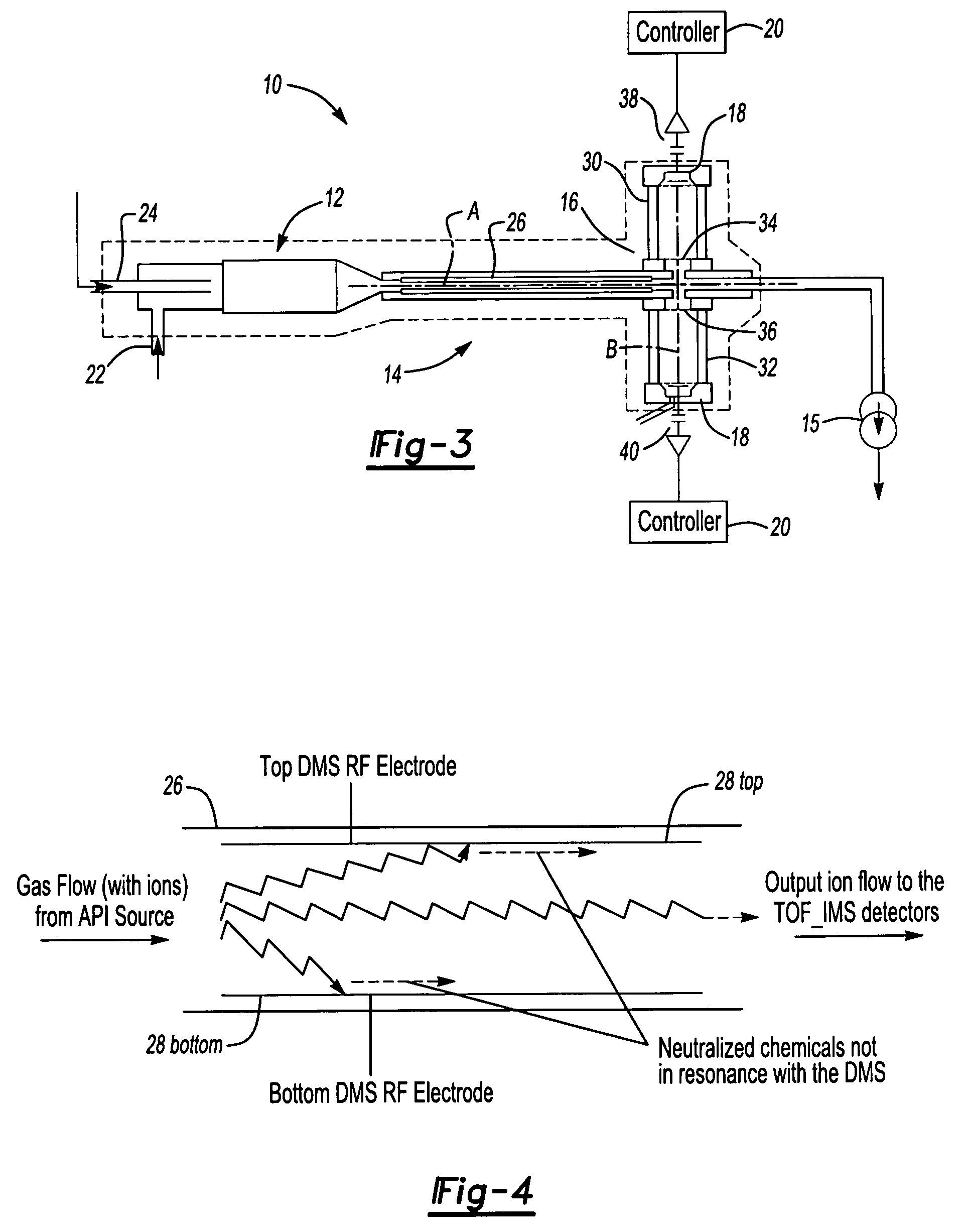
[0016]FIG. 1 illustrates a general schematic view of a chemical sensing system 10. The sensing system 10 generally includes an atmospheric pressure ionization (API) system 12, a Differential Mobility Spectrometry (DMS) system 14, and a Time-of-Flight Ion Mobility Spectrometry (TOF-IMS) system 16. The TOF-IMS system 16 includes an ion detector system 18, which communicates with a controller 20 (also schematically illustrated in FIG. 2). Instrument control and analysis functions to detect specified lists of TICs and CWAs are programmed into the controller 20 and are reconfigurable via a communication system 21. The communication system 21 could perhaps be via serial or parallel interface, could be established via a Wi-Fi network, or could be based on a self-configuring RF network, with software for remote commanding and data analysis layered onto the selected communications link.

[0017]Generally, the API system 12 rejects simple hydrocarbon interferences while efficiently ionizing targ...


PUM


Abstract

A DMS-IMS chemical sensing system employs two ion-separation technologies in tandem to extract signals of specific chemicals from the glut of signals present. The sensing system generally includes an atmospheric pressure ion generation system, a Differential Mobility (DMS) system, a time-of-flight IMS (TOF-IMS) system, and an ion detector system. The DMS extracts a narrow range of trace chemicals from an environmental sample for subsequent analysis, and a TOF-IMS then analyzes the resulting narrow range of isolated chemicals, allowing compound-specific detection thresholds at sub-ppb concentrations.

Description

BACKGROUND OF THE INVENTION[0001]The present invention relates to a chemical sensing system, and more particularly to a sensing system that utilizes two ion-separation technologies in tandem to detect specific chemicals in the presence of common environmental chemical backgrounds.[0002]Sensing to identify and quantitate specific chemicals is of interest for a variety of purposes, including assuring human safety in environments that may contain threats from Toxic Industrial Chemicals (TICs) or Chemical Warfare Agents (CWAs), and in industrial process control. Chemical sensing for environmental monitoring must be compatible with safety requirements, as specifically promulgated by OSHA and other government organizations through time-weighted average Permissible Exposure Limits (PELs). These standards are also broadly applied to potential chemical threats. Many TICs, including pesticides, acid vapors, and carcinogens, and the CWAs have PELs that range from part per million (ppm) and par...

Claims


Application Information

Patent Timeline
Patent Type & Authority Patents(United States)
IPC IPC(8): H01J49/00
CPCG01N27/624
Inventor BURCHFIELD, DAVID E.NIU, H. WILLIAMHEPPNER, RICHARD A.
Owner HAMILTON SUNDSTRAND CORP
Learn More