
Transformer and display device using the same

a technology of display device and transformer, applied in the field of transformer, can solve the problem of difficult design of switching transformers with small leakage inductance, and achieve the effect of reducing leakage inductan

Active Publication Date: 2014-06-10
SOLUM CO LTD
View PDF25 Cites 3 Cited by
  • Summary
  • Abstract
  • Description
  • Claims
  • Application Information

AI Technical Summary

Benefits of technology

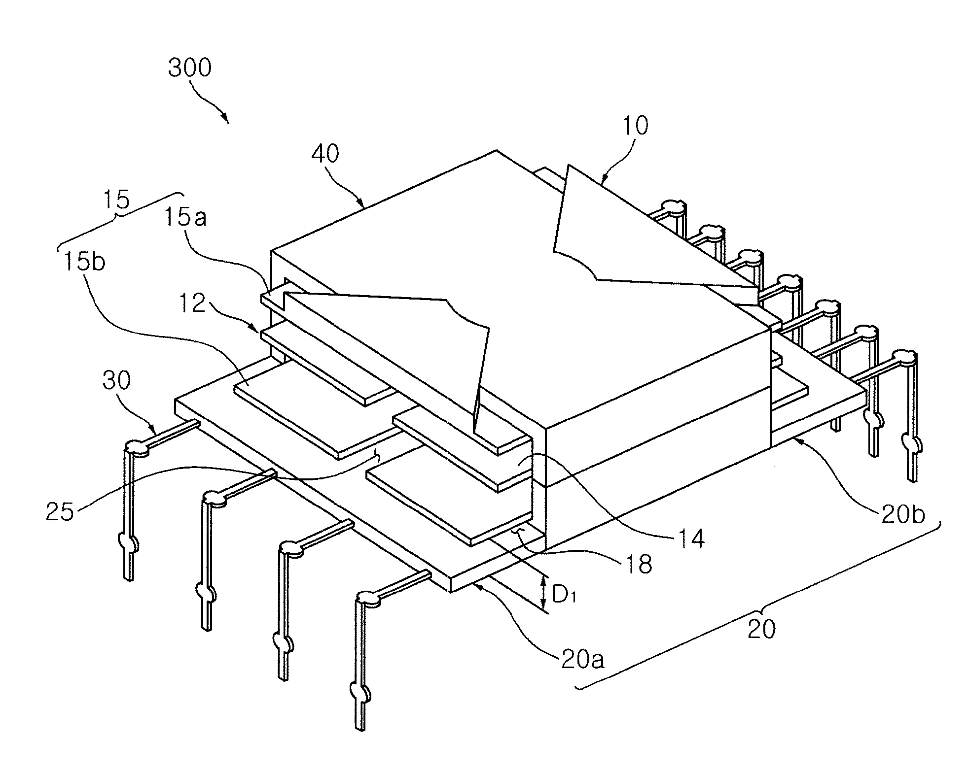
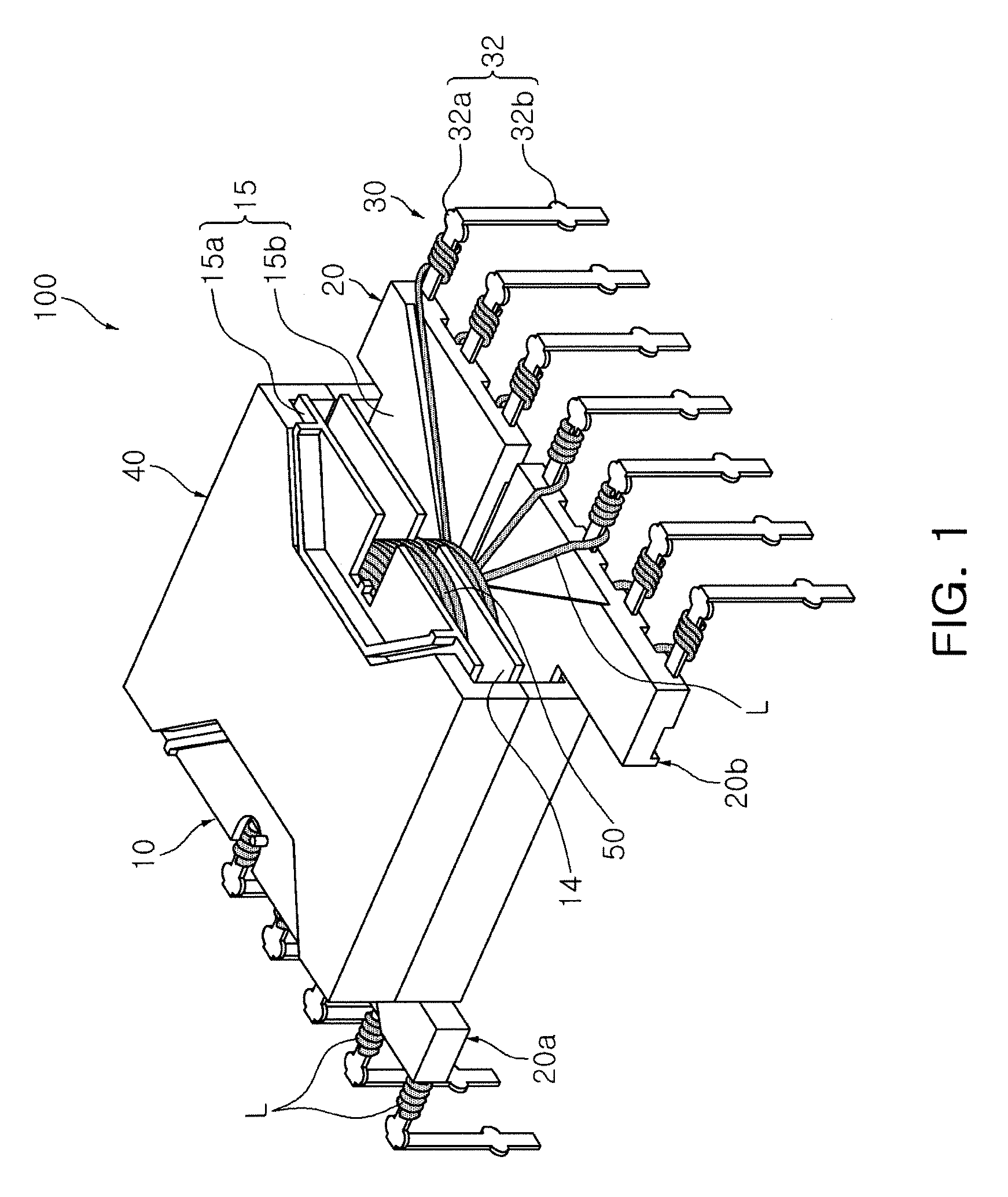
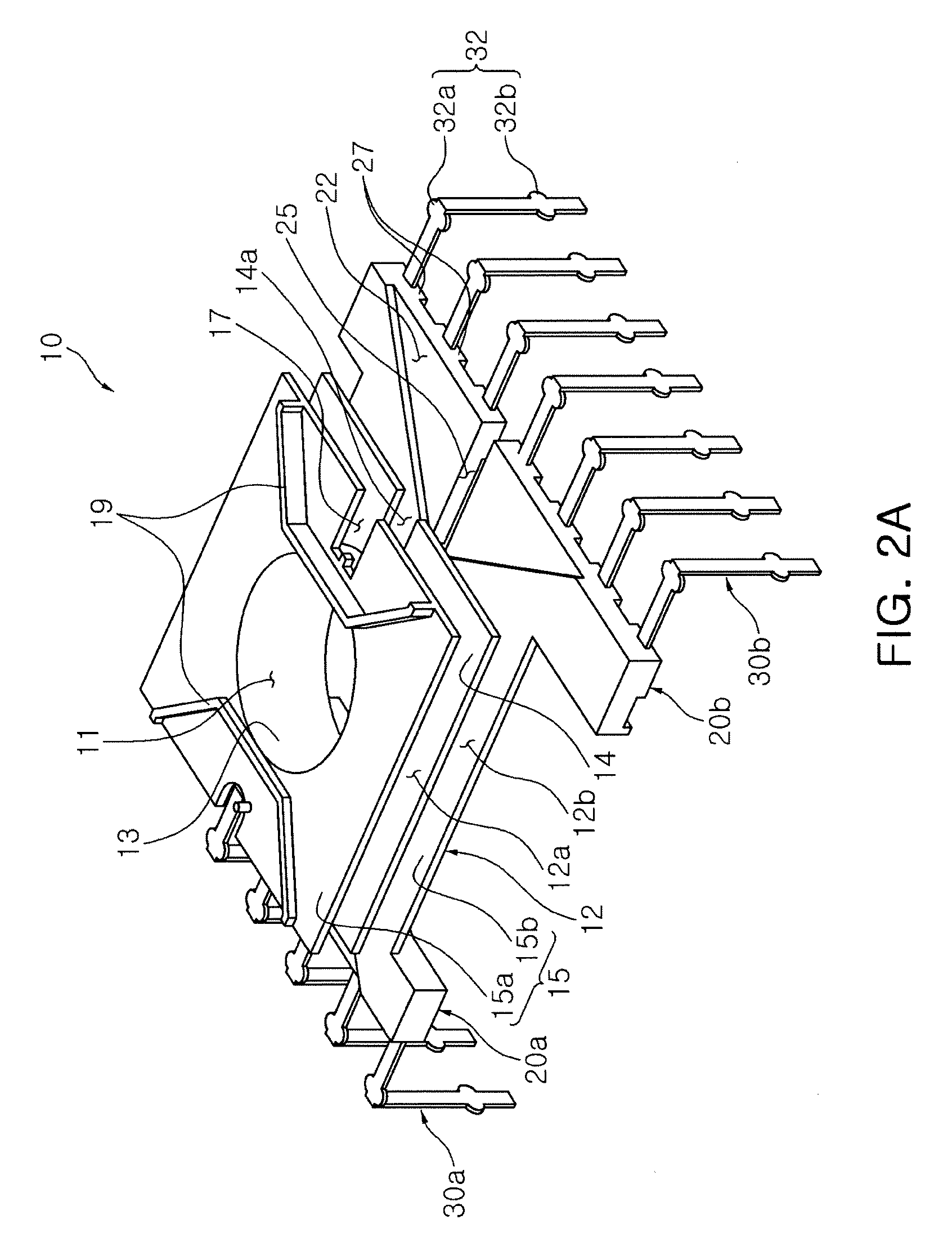
The invention is about a transformer that prevents leakage inductance. This means that the transformer has a way to minimize the amount of magnetic field that is affected by magnetic flux. This helps to improve the efficiency of the transformer.

Problems solved by technology

However, in accordance with the miniaturization of the switching transformer, it may be difficult to design a switching transformer having a small leakage inductance.

Method used


Image

  • Transformer and display device using the same
  • Transformer and display device using the same
  • Transformer and display device using the same

Examples


Embodiment Construction

[0044]Prior to a detailed description of the present invention, the terms or words, which are used in the specification and claims to be described below, should not be construed as having typical or dictionary meanings. The terms or words should be construed in conformity with the technical idea of the present invention on the basis of the principle that the inventor(s) can appropriately define terms in order to describe his or her invention in the best way. Embodiments described in the specification and structures illustrated in drawings are merely exemplary embodiments of the present invention. Thus, it is intended that the present invention covers the modifications and variations of this invention, provided they fall within the scope of their equivalents at the time of filing this application.

[0045]Exemplary embodiments of the present invention will be described in detail with reference to the accompanying drawings. The same reference numerals will be used throughout to designate...


PUM

PropertyMeasurementUnit
frequencyaaaaaaaaaa
outer diameteraaaaaaaaaa
distanceaaaaaaaaaa

Abstract

There is provided a transformer having a minimized leakage inductance. The transformer includes: a winding part including a pipe shaped body part having a plurality of coils wound therearound and flange parts extended from both ends of the body part in an outer diameter direction thereof; and a core coupled to the winding part, wherein a flange part formed at one end of the body part includes at least one lead groove, and the coils are led to the outside of the winding part through the at least one lead groove.

Description

CROSS-REFERENCE TO RELATED APPLICATIONS[0001]This application claims the priority of Korean Patent Application No. 10-2011-0057275 filed on Jun. 14, 2011, in the Korean Intellectual Property Office, the disclosure of which is incorporated herein by reference.BACKGROUND OF THE INVENTION[0002]1. Field of the Invention[0003]The present invention relates to a transformer, and more particularly, to a transformer having a minimized leakage inductance.[0004]2. Description of the Related Art[0005]Various kinds of power supplies are required in various electronic devices such as a television (TV), a monitor, a personal computer (PC), an office automation (OA) device, and the like. Therefore, these electronic devices generally include power supplies converting an alternating current (AC) power supplied from the outside into a power required for each electronic appliance.[0006]Among power supplies, a power supply using a switching mode (for example, a switch mode power supply (SMPS)) has mainl...

Claims


Application Information

Patent Timeline
Patent Type & Authority Patents(United States)
IPC IPC(8): H01F27/30
CPCH01F27/325H01F2005/022H01F5/04H01F27/28H01F27/24
Inventor LEE, YOUNG MINWON, JAE SUNKIM, JONG HAEKIM, DEUK HOONPARK, GEUN YOUNG
Owner SOLUM CO LTD
Learn More