
Front light system for reflective displays

Active Publication Date: 2014-06-03
E INK CALIFORNIA
View PDF41 Cites 44 Cited by
  • Summary
  • Abstract
  • Description
  • Claims
  • Application Information

AI Technical Summary

Benefits of technology

The front light system is a thin, flexible lighting system that can be used on a range of devices. It provides uniform lighting with high efficiency, resulting in low power requirements. The technology is especially useful for use in keyboards where a flexible reflective display is placed on top of a touch-sensitive surface.

Problems solved by technology

First, since the light is strongest at the point of entry into the light guide film, the light tends to fall off in intensity rapidly at points which are further from the illuminating source.
Although such a system provides some degree of improvement in lighting uniformity, the uniformity, however, is still unsatisfactory, and the system must be customized for every application.
Secondly, since this lighting system is based on scattering phenomenon, any scratch or piece of dirt in the light guide film also scatters the light which shows up as defects.
As a result, it is very difficult for such a system to function properly.
In addition, if a flexible front light is required, the front light system must be very thin; but a thin front light guide film exacerbates non-uniformity of the light along the length of the light guide film as described above.

Method used


Image

  • Front light system for reflective displays
  • Front light system for reflective displays
  • Front light system for reflective displays

Examples


Embodiment Construction

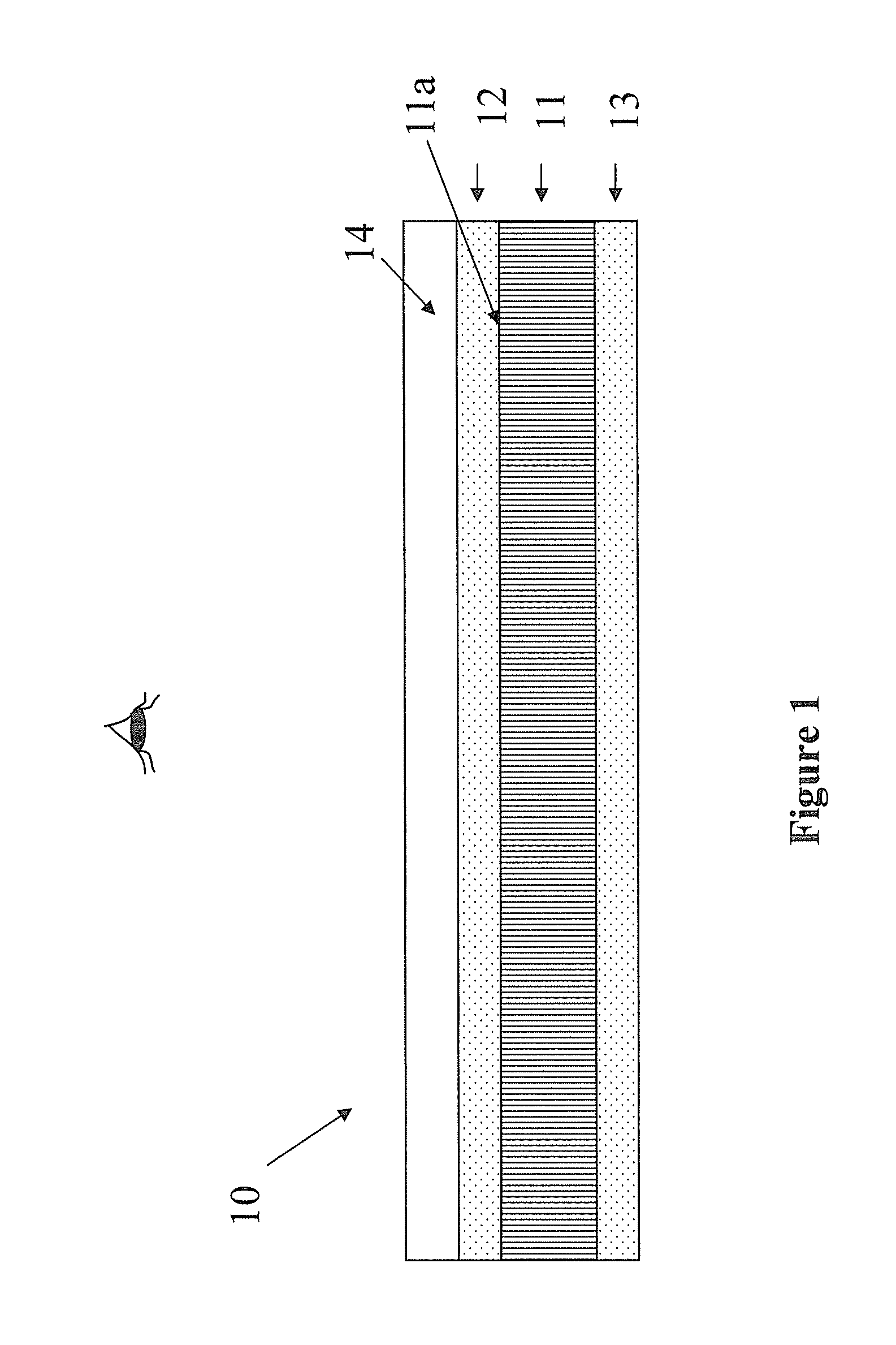
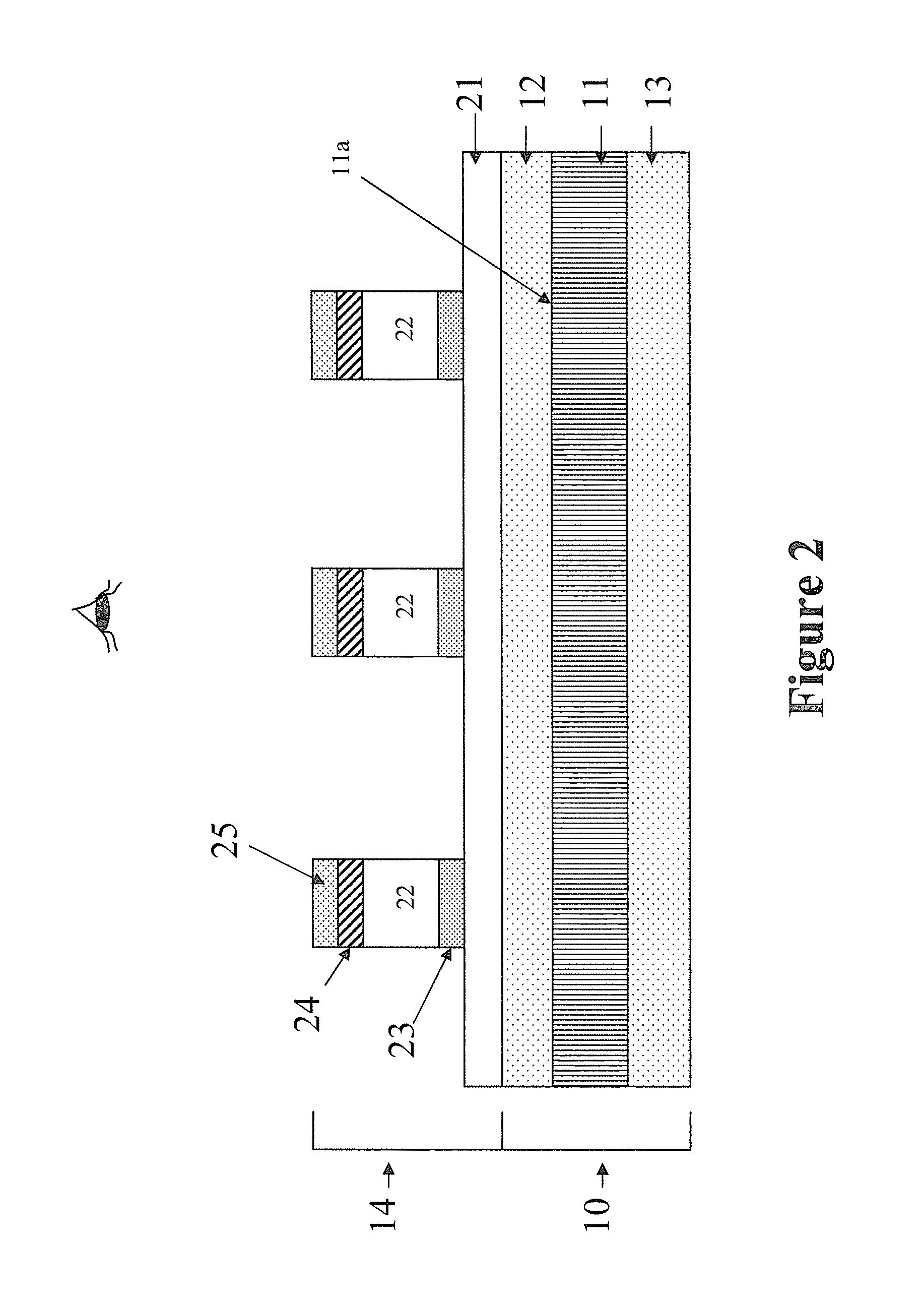
[0018]FIG. 1 is a cross-section view of a reflective display (10). The display comprises a display film (11) sandwiched between a first electrode layer (12) and a second electrode layer (13). One of the electrode layers (12 or 13) is transparent for viewing. In FIG. 1, the side of electrode layer 12 is the viewing side.

[0019]When the electrode layer is transparent, the electrode layer is usually formed from ITO (indium tin oxide). A front light film (14) of the present invention is formed or laminated over the viewing surface of the reflective display (10).

[0020]In a passive matrix display, the electrode layers (12 and 13) may be electrode layers having conductive lines formed thereon.

[0021]In a direct drive display, one of the electrode layers is a common electrode layer and the other electrode layer is a backplane comprising segmented electrodes or pixellated electrodes. In other words, the display film (11) is sandwiched between a common electrode layer and a backplane. The commo...


PUM


Abstract

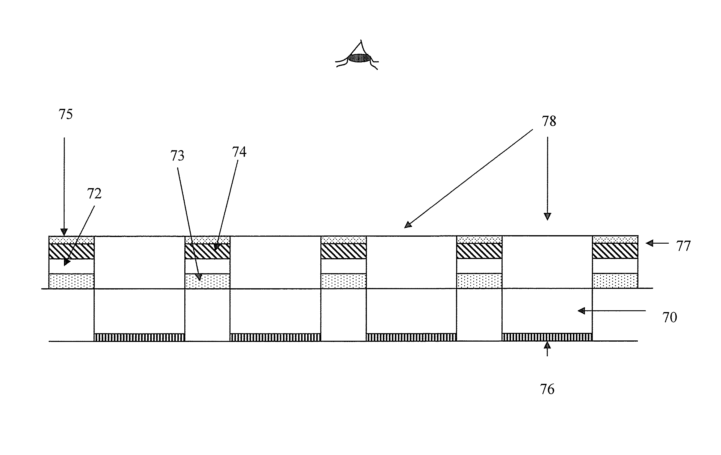
The present invention relates to a front light system which can be built with thin film light emitting diodes (LEDs), such as organic light emitting diodes (OLEDs) or electro-luminescent light emitting diodes. The front light system may be built on a thin and flexible substrate and can generate lighting of satisfactory uniformity and with high efficiency. The system also can potentially be inexpensive. The front light system of the present invention is particularly suitable for keymat applications wherein a flexible reflective display on top of a touch sensitive surface or device, is used as an output device.

Description

[0001]This application claims priority to U.S. provisional application No. 60 / 953,410, filed Aug. 1, 2007; the content of which is incorporated herein by reference in its entirety.BACKGROUND[0002]Reflective displays require a front light system to facilitate viewing of images displayed. The front lighting for reflective displays normally consists of a light guide film attached to the front surface of the display. This light guide film has an illumination source placed at the edge of the light guide film and the light is guided within the film by total internal reflection of the surface along the light guide film, so that the light crosses the front of the display. Part of the surface of the light guide has a light scattering structure which causes light inside the light guide film to be scattered out of the film to strike the display surface. Such a system usually has a slightly rough surface which may be the display itself that is index matched to the light guide film, or has an ar...

Claims


Application Information

Patent Timeline
IPC IPC(8): G06F3/041
CPCG06F3/0412G06F3/041G06F1/1643G06F1/1662
Inventor SPRAGUE, ROBERT, A.
Owner E INK CALIFORNIA
Learn More