System and method for positioning implantable medical devices within coronary veins

a technology of coronary veins and medical devices, applied in the field of visualization and delivery systems, can solve the problems of unnecessarily destroying much of the viable tissue surrounding the site, unable to accurately and reliably contact the various curved shapes one encounters in the endocardial lining, and unable to customize the shape, so as to minimize the chance of tissue damage, soft atraumatic tip, and more kink resistant

Inactive Publication Date: 2014-05-27
MEDTRONIC INC
View PDF72 Cites 1 Cited by
  • Summary
  • Abstract
  • Description
  • Claims
  • Application Information

AI Technical Summary

Benefits of technology

The present invention is a sheath that is designed for use in placing leads and other devices within the coronary sinus or branch veins. The sheath has a soft distal end to minimize tissue damage and is kink-resistant as it is pushed through the vascular system during an implant procedure. The sheath is readily pushable and can easily navigate the torturous curves of the venous system. It also has a small outer diameter that allows for easy advancement within the coronary sinus and branch veins without damaging tissue. The sheath is slittable and uses braid materials that maintain its beneficial properties. These technical features provide a sheath that is easier to use and remove from the body after a lead or other device has been positioned at a final implant location.

Problems solved by technology

If the site is not accurately mapped, much of the viable tissue surrounding the site will be unnecessarily destroyed.
However, despite the advantages of these sensing devices and guiding catheters, it remains quite difficult to accurately and reliably contact the various curved shapes one encounters in the endocardial lining.
This is due to the frequent inability to customize the shape of their distal portion, or at least the inability to instantaneously and accurately adjust their shape upon demand during deployment to conform to the shape of the tissue of interest.
Many problems exist with reliably and accurately placing medical electrical leads and other similar devices such as catheters within the heart and associated vasculature.
For instance, when placing transvenous leads or catheters, it is often difficult to engage the coronary sinus and sub-select the proper vessel into which the lead or catheter is to eventually be placed.
Moreover, once placed, transvenous devices suffer from a relatively high rate of dislodgment from sites adjacent to, or on, the epicardium.
Such dislodgement may result in a loss of capture or, at best, a reduction of the degree of electrical coupling between the electrode and the myocardium.

Method used


Image

  • System and method for positioning implantable medical devices within coronary veins
  • System and method for positioning implantable medical devices within coronary veins
  • System and method for positioning implantable medical devices within coronary veins

Examples


Embodiment Construction

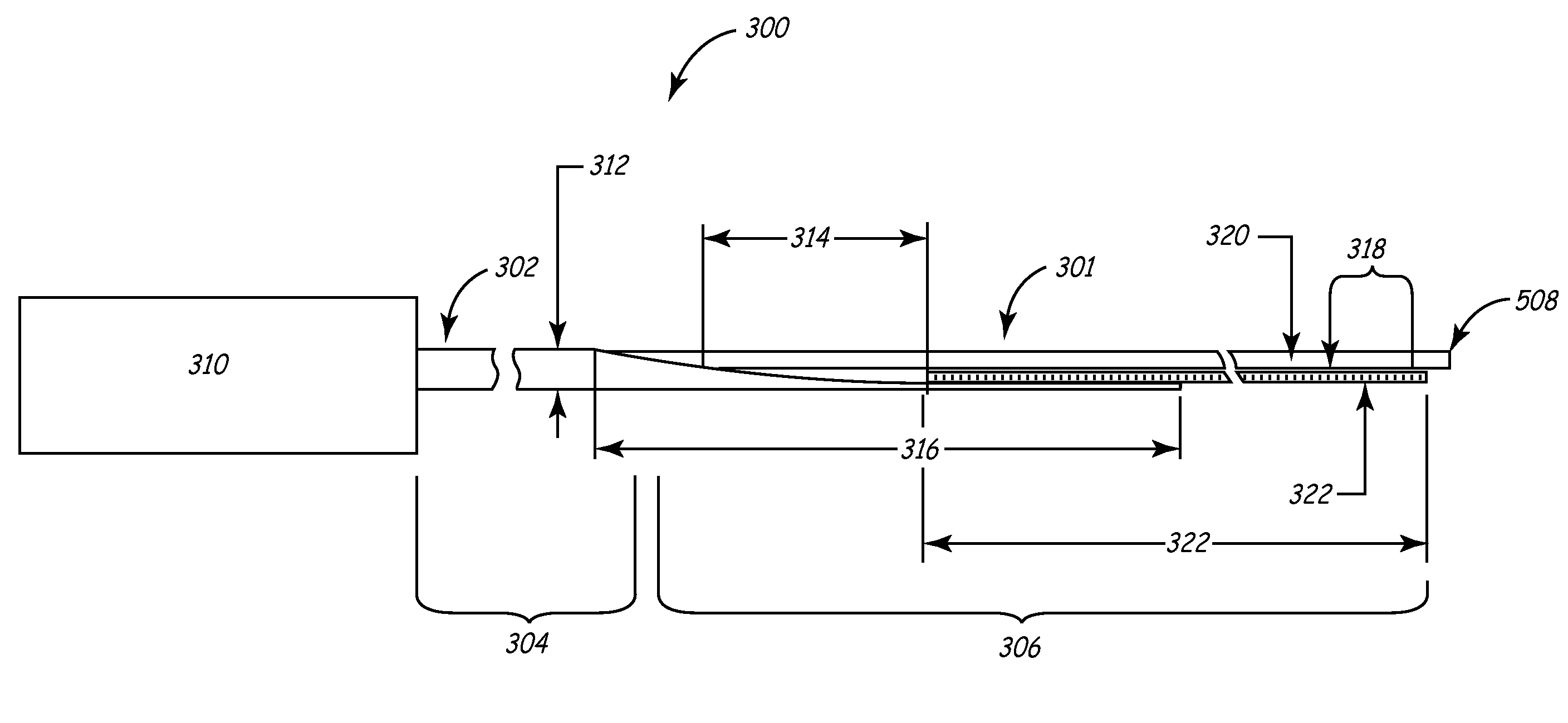
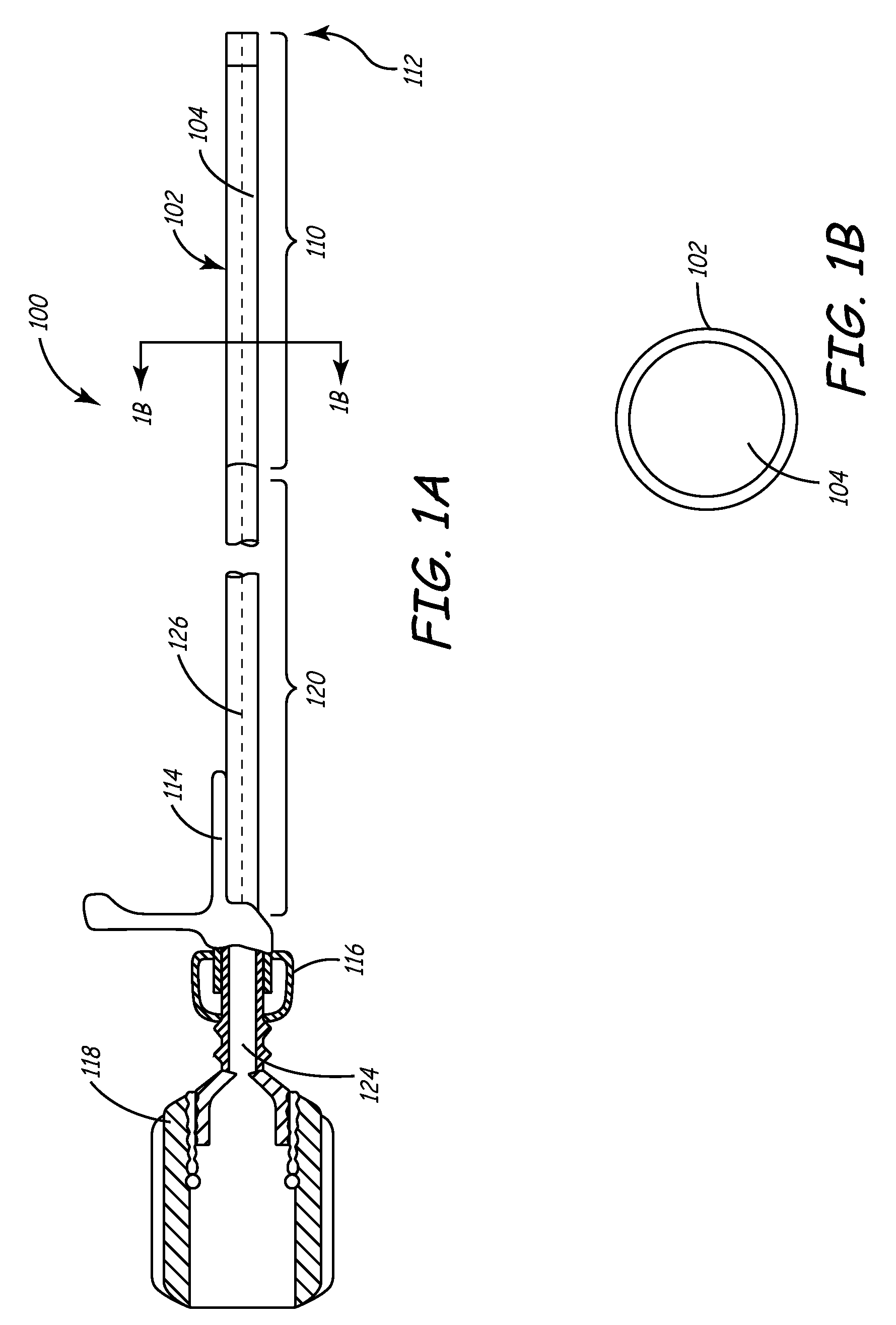
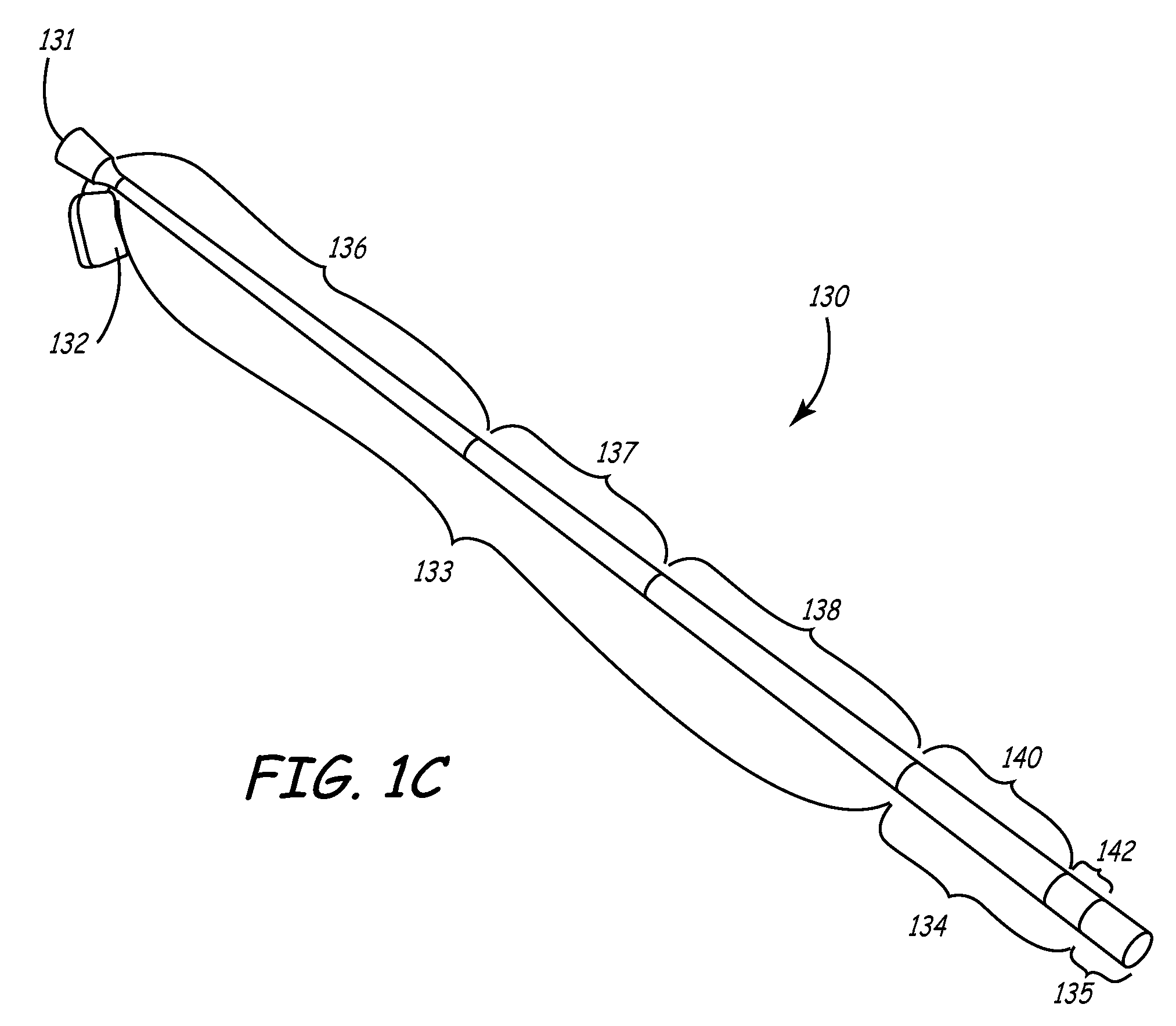
[0041]This invention involves a method and system for intralumenal visualization and deployment of implantable medical devices (IMDs) such as transvenous leads, electrophysiology catheters and the like to various targeted regions of the body. The inventive system includes a sheath, which may be used along with a balloon catheter and associated deflection mechanism, and a micro-deflection device for highly accurate placement of the lead, catheter, or other device once the area of interest has been visualized.

[0042]The following description sets forth several embodiments of the inventive sheath, followed by a description of additional components that may be used with the sheath to place a transvenous lead into the coronary veins. Although the description sets forth several methods for using the sheath, as well as an exemplary set of system components for use in conjunction with the current invention, other system configurations, adaptations, and methods of use are within the scope of ...


PUM


Abstract

An improved system and method for placing implantable medical devices (IMDs) such as leads within the coronary sinus and branch veins is disclosed. In one embodiment, a slittable delivery sheath and a method of using the sheath are provided. The sheath includes a slittable hub, and a substantially straight body defining an inner lumen. The body comprises a shaft section and a distal section that is distal to, and softer than, the shaft section. A slittable braid extends adjacent to at least a portion of one of the shaft section and the distal section. In one embodiment of the invention, the sheath further includes a transition section that is distal to the shaft section, and proximal to the distal section. The transition section is softer than the shaft section, but stiffer than the distal section.

Description

RELATED APPLICATIONS[0001]This application is a divisional of U.S. patent application Ser. No. 10 / 131,436, filed Apr. 25, 2002, now U.S. Pat. No. 7,497,844, which is a continuation-in-part of commonly-assigned U.S. patent application Ser. No. 09 / 822,678 filed Mar. 30, 2001, now U.S. Pat. No. 6,743,227, which is related to, and claims the benefit of, provisionally-filed U.S. Patent Application Ser. No. 60 / 193,695 filed Mar. 31, 2000, entitled “Intraluminal Visualization System with Deflectable Mechanism”.[0002]Cross-reference is hereby made to commonly assigned related U.S. Applications, filed concurrently herewith, U.S. patent application Ser. No. 10 / 131,388, now U.S. Pat. No. 6,836,687, entitled “METHOD AND SYSTEM FOR DELIVERY OF A MEDICAL ELECTRICAL LEAD WITHIN A VENOUS SYSTEM”, and U.S. patent application Ser. No. 10 / 131,672, now U.S. Pat. No. 6,733,500, entitled “METHOD AND SYSTEM FOR DELIVERING A MEDICAL ELECTRICAL LEAD WITHIN A VENOUS SYSTEM”.BACKGROUND OF THE INVENTION[0003]T...

Claims


Application Information

Patent Timeline
Patent Type & Authority Patents(United States)
IPC IPC(8): A61M25/06A61B18/14A61M25/00A61M5/178A61N1/05A61M25/01
CPCA61M25/0054A61M2025/0042A61M2025/0161A61M25/005A61M25/0141A61M2025/0081A61B2017/22038A61M2025/1052A61M2025/1079A61N2001/0585A61M25/0138A61M25/0668A61N2001/0578A61M25/0051A61M2025/0047A61N1/056A61M25/0147A61M2025/0681A61B18/1492A61M25/008A61B2018/00386
Inventor SPEAR, STANTEN C.KELLEY, JAMES F.GARDESKI, KENNETH C.SERAJ, MOHMOUD K.CHAN, ERIC K. Y.
Owner MEDTRONIC INC
Why Eureka
Try Eureka