Electron microscope with an emitter operating in medium vacuum

a technology of electron microscope and emitter, which is applied in the field of electron microscope, can solve the problems of increasing the size and weight of the existing electron microscope, limiting the number of potential applications and users affecting the efficiency of the electron microscope, so as to facilitate faster imaging or writing

Inactive Publication Date: 2014-05-20
DLA INSTR
View PDF14 Cites 5 Cited by
  • Summary
  • Abstract
  • Description
  • Claims
  • Application Information

AI Technical Summary

Benefits of technology

[0010]Additionally, the electron microscope may be portable. For example, the electron microscope may be hand held. In some embodiments, the housing has an opening defined by an edge, and the electron microscope includes a seal (such as a sliding seal or an airbearing) that is mechanically coupled to the housing, which removeably mechanically couples the housing to a surface external to the electron microscope. This seal may facilitate displacement of the housing along the surface when the housing is mechanically coupled to the surface.
[0018]Note that the electron microscope may include multiple electron emitters and associated housings, which facilitate faster imaging or writing. Additionally or separately, at least the electron emitter and / or the housing may be fabricated using a micro-electromechanical system (MEMS) fabrication technology.

Problems solved by technology

However, the vacuum pumps and associated hardware (such as valves) used to create and maintain such reduced pressures (such as turbo-molecular pumps or diffusion pumps) are expensive, can make existing electron microscopes difficult to use, and can increase the size and weight of the existing electron microscopes.
These characteristics can limit the number of potential applications and users of electron microscopes.

Method used


Image

  • Electron microscope with an emitter operating in medium vacuum
  • Electron microscope with an emitter operating in medium vacuum
  • Electron microscope with an emitter operating in medium vacuum

Examples


Embodiment Construction

[0034]The following description is presented to enable any person skilled in the art to make and use the invention, and is provided in the context of a particular application and its requirements. Various modifications to the disclosed embodiments will be readily apparent to those skilled in the art, and the general principles defined herein may be applied to other embodiments and applications without departing from the spirit and scope of the present invention. Thus, the present invention is not limited to the embodiments shown, but is to be accorded the widest scope consistent with the claims.

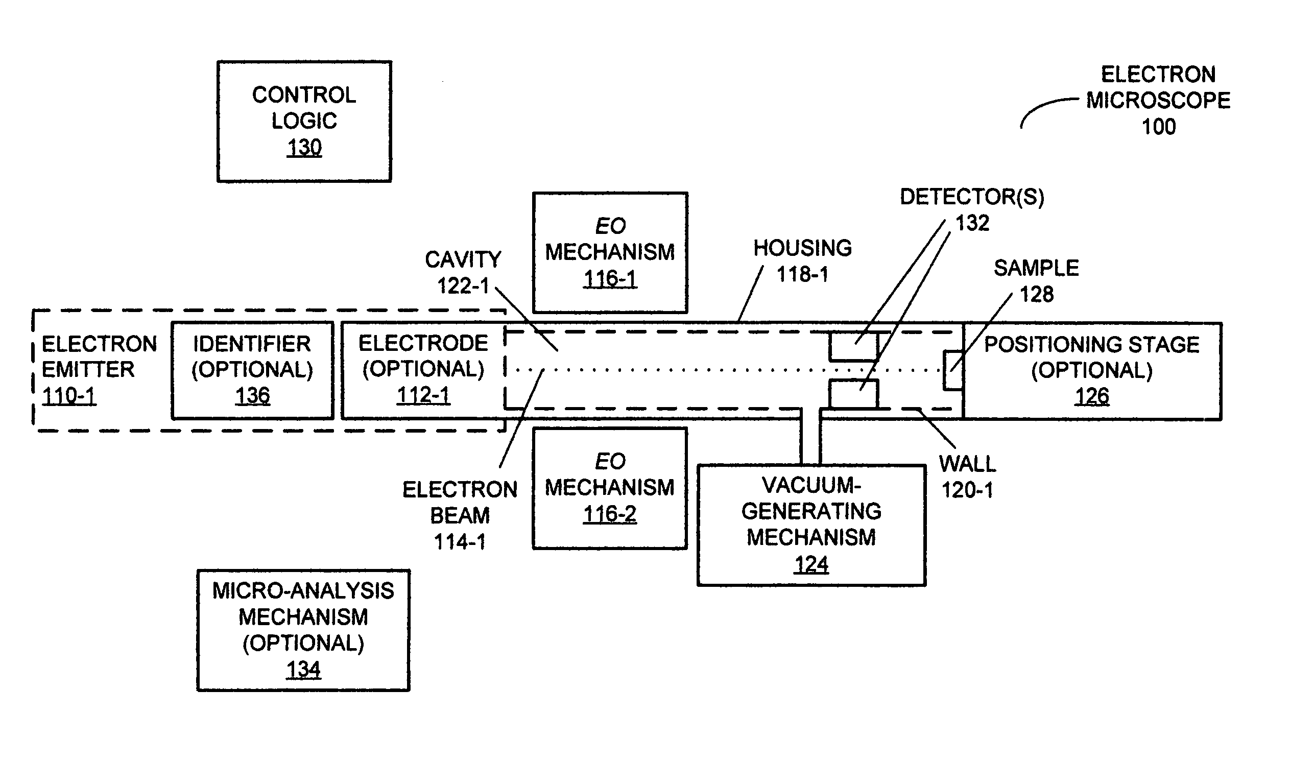
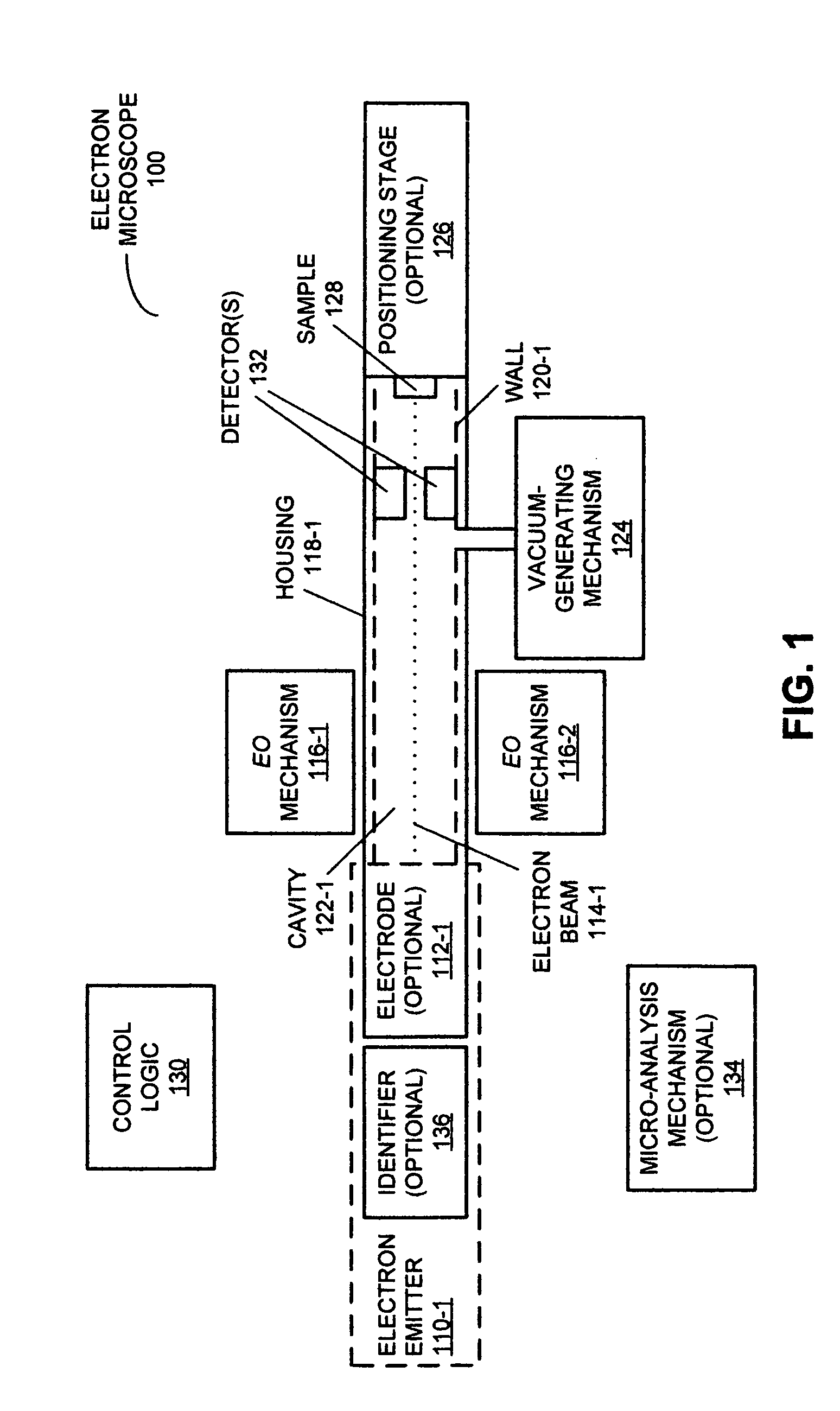
[0035]Embodiments of an electron microscope, associated methods, and of an x-ray source are described. This electron microscope includes an electron emitter that has an evaporation or sublimation rate that is significantly less than that of tungsten or lanthanum hexaboride at the reduced pressures around the electron emitter during operation of the electron microscope. As a consequence, the e...


PUM


Abstract

An electron microscope is described. This electron microscope includes an electron emitter that has an evaporation or sublimation rate that is significantly less than that of tungsten at the reduced pressures around the electron emitter during operation of the electron microscope. As a consequence, the electron microscope may be able to operate at reduced pressures that are much larger than those in existing electron microscopes. For example, at least during the operation the reduced pressure in the electron microscope may be greater than or equal to a medium vacuum. This capability may allow the electron microscope to use a roughing pump to provide the reduced pressure, thereby reducing the cost and complexity of the electron microscope, and improving its reliability. In addition, the size of the electron microscope may be reduced, which may enable a hand-held or portable version of the electron microscope.

Description

CROSS REFERENCE TO RELATED APPLICATIONS[0001]This application claims priority under 35 U.S.C. 119(e) to U.S. Provisional Application Ser. No. 61 / 268,695, entitled “Electron Microscope With Emitter Operating in Low Vacuum,” by David L. Adler, filed on Jun. 14, 2009, the contents of which are herein incorporated by reference.FIELD OF THE INVENTION[0002]The present disclosure relates generally to an electron microscope and associated methods. More specifically, the present disclosure relates to an electron microscope with an emitter that can operate at a pressure greater than or equal to a medium vacuum.BACKGROUND[0003]Electron microscopes are widely used in micro-analysis because of their high depth of field and resolution. Typically, existing electron microscopes use electron-emitter materials that have a high evaporation or sublimation rate in environments that contain oxygen, such as tungsten or lanthanum hexaboride. Consequently, to extend the life of the electron emitter, during ...

Claims


Application Information

Patent Timeline
Patent Type & Authority Patents(United States)
IPC IPC(8): H01J37/28
CPCH01J2237/2605H01J37/06H01J37/26H01J37/28
Inventor ADLER, DAVID, L.
Owner DLA INSTR
Why Eureka
Try Eureka