Hot swap fan module

a technology of fan module and heat dissipation fan, which is applied in the direction of positive displacement liquid engine, piston pump, liquid fuel engine, etc., can solve the problems of system failure and limited space of heat dissipation fan, and achieve the effect of reducing volume, simplifying structure and fast assembly

Inactive Publication Date: 2014-05-20
DELTA ELECTRONICS INC
View PDF16 Cites 9 Cited by
  • Summary
  • Abstract
  • Description
  • Claims
  • Application Information

AI Technical Summary

Benefits of technology

[0006]The objective of the invention is to provide a hot swap fan, with simplified structure to provide fast assembly, to reduce volume, and to reduce fabrication costs. In addition, connectibility and manufacturing tolerance between a contact terminal and a corresponding terminal of the system are enhanced.
[0007]Another objective of the invention is to provide a hot swap fan with more convenience and more safety.
[0018]In the invention, the end of the puller structure pivots on the fan, and the other end of the puller structure has a holding ring on the bent portion. Only one puller structure is needed, by using a finger, the fan can be quickly assembled or disassembled. The simplified structure of the hot swap fan minimizes the overall volume and cost at the same time. Further, the holding ring is formed on the bent portion, such that the elasticity of the puller structure reduces the gap between a contacting terminal and a corresponding terminal of the system, enhancing the connectibility and manufacturing tolerance between the two.
[0019]In addition, the fan guard and the puller structure are integrated into the hot swap fan. Only a small amount of additional space is required for the system to be firmly covered, and to be more convenient and safe.

Problems solved by technology

When an electronic device is in operation, heat produced increases ambient temperature in the entire system, affecting stability and possibly causing system failure.
However, the heat dissipating fan is arranged in limited space within the system.

Method used


Image

  • Hot swap fan module
  • Hot swap fan module
  • Hot swap fan module

Examples


Embodiment Construction

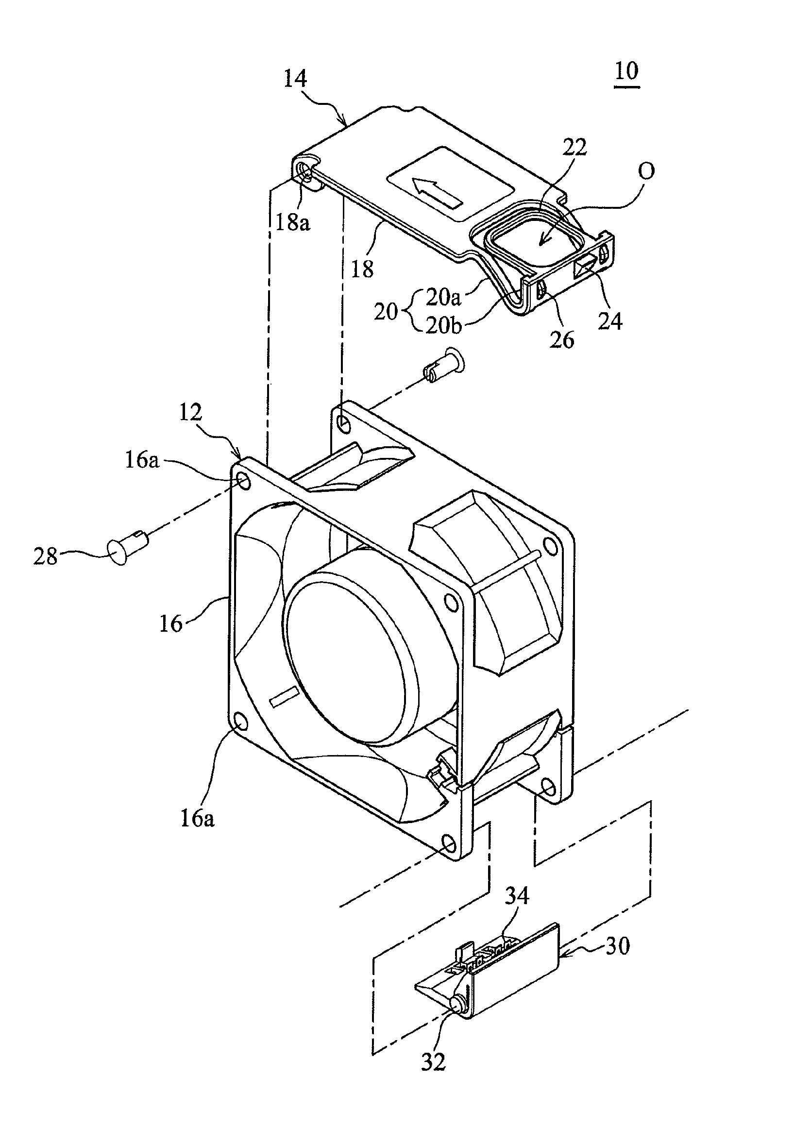
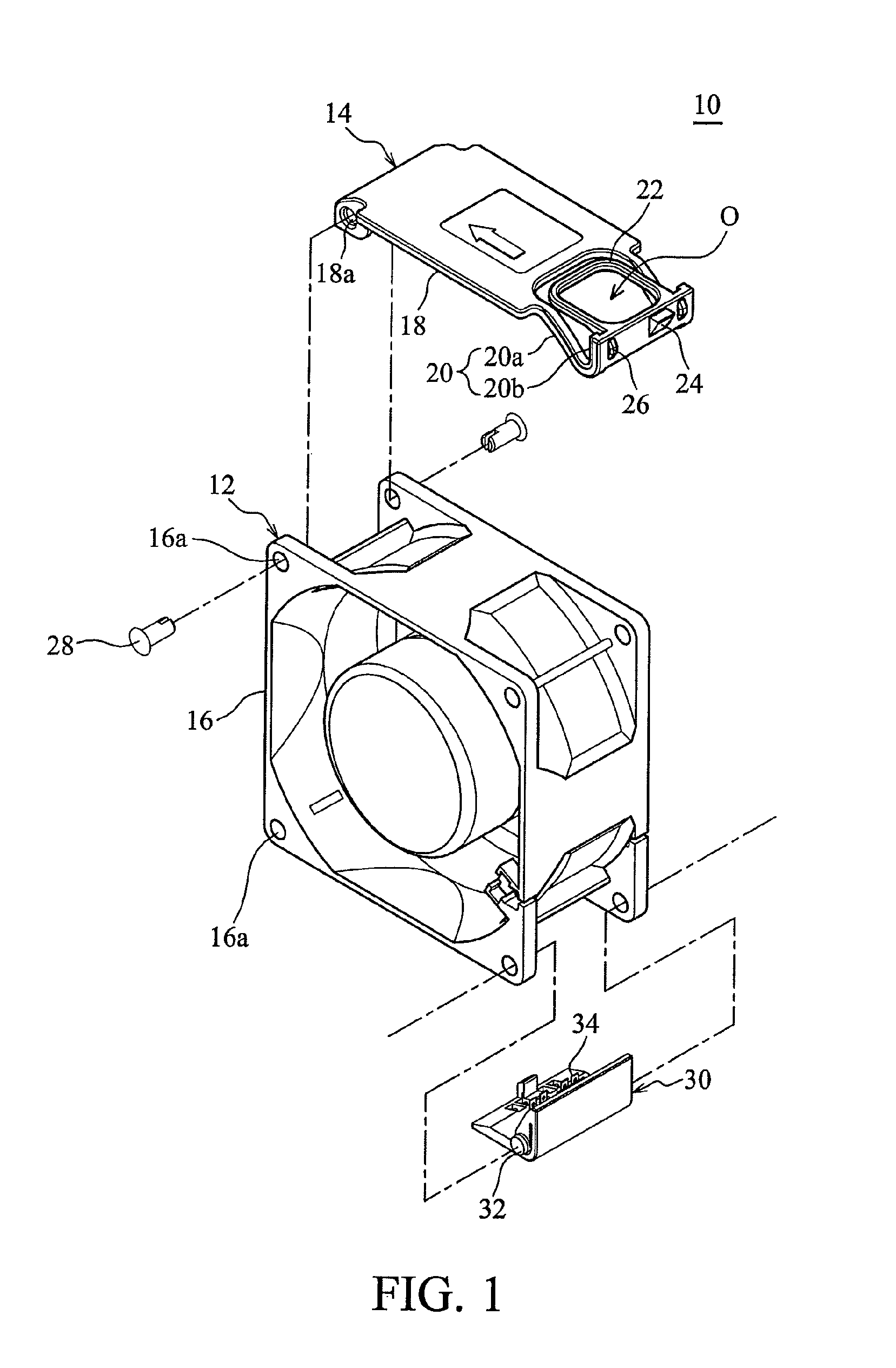
[0027]FIG. 1 is an exploded view of an embodiment of a hot swap fan module 10 of the present invention.

[0028]As shown in FIG. 1, the hot swap fan module 10 comprises a fan 12 and a puller structure 14. The fan 12 has an inlet surface, an outlet surface, and a side surface connecting the inlet surface and the outlet surface. A plurality of connecting holes 16a is formed on a frame 16 of the fan 12.

[0029]The puller structure 14 is elastic / flexible material, such as metal or plastic. In order to match the appearance of the frame 16, the puller structure 14 comprises a base 18 and a bent portion 20 on an end of the base 18, disposed on the side surface of the fan 12. The side surface of the fan 12 may be a top-surface of the side surface of the fan 12.

[0030]An other end of the base 18 has a pivoting hole 18a for pivoting an end of the puller structure 14 on the frame 16 of the fan 12. The base 18 can be a flat structure, or a flat structure with a bent end. The pivoting hole 18a is corr...


PUM


Abstract

A hot swap fan includes a fan and a puller structure. The puller structure covers a side surface of the fan. The puller structure includes a base, a holder, and a fixing structure. A first end of the base is pivoted to the fan. The holder and the fixing structure are on a second end of the base.

Description

BACKGROUND OF THE INVENTION[0001]1. Field of the Invention[0002]The present invention relates to a hot swap fan and a puller structure thereof, and a fan module with a hot swap fan.[0003]2. Description of the Related Art[0004]When an electronic device is in operation, heat produced increases ambient temperature in the entire system, affecting stability and possibly causing system failure. A heat-dissipating device, such as a heat-dissipating fan, is used to stabilize system operating under a stabilized ambient temperature. In order to avoid system shutdown when replacing damaged fans, a hot swap fan is developed to allow the system to operate in 24 hours.[0005]However, the heat dissipating fan is arranged in limited space within the system. Simplifying components to allow the fan to be assembled with hot swap ability is needed.BRIEF SUMMARY OF INVENTION[0006]The objective of the invention is to provide a hot swap fan, with simplified structure to provide fast assembly, to reduce vol...

Claims


Application Information

Patent Timeline
Patent Type & Authority Patents(United States)
IPC IPC(8): F04B35/04
CPCF04D29/601
Inventor LU, JA-JENGTAO, PENG-CHUCHUANG, TE-TSAIHUANG, WEN-SHI
Owner DELTA ELECTRONICS INC
Why Eureka
Try Eureka