
Rotor oscillation preventing structure and steam turbine using the same

a technology of preventing structure and preventing plate, which is applied in the direction of machines/engines, stators, liquid fuel engines, etc., can solve the problems that the above-mentioned conventional art may not the whirl preventing plate cannot satisfactorily exhibit its own function, so as to reduce the occurrence potential of steam whirl, reduce the absolute velocity component, and reduce the whirl velocity of leakage flow

Active Publication Date: 2014-05-20
MITSUBISHI POWER LTD
View PDF18 Cites 4 Cited by
  • Summary
  • Abstract
  • Description
  • Claims
  • Application Information

AI Technical Summary

Benefits of technology

This solution effectively reduces the whirl velocity of leakage flow entering labyrinth seals, minimizing steam whirl and enhancing turbine efficiency by converting lost whirl energy into usable power, while maintaining cost-effectiveness through standard machining processes.

Problems solved by technology

However, the rotor oscillation preventing structure as the above-mentioned conventional art may not satisfactorily exhibit its own function in some cases depending on the trajectory of the leakage flow.
In such a case, the whirl flow will not reach the whirl preventing plate installed on the vertical surface of the outer circumferential side stationary wall, and thereby the whirl preventing plate cannot satisfactorily exhibit its own function.

Method used


Image

  • Rotor oscillation preventing structure and steam turbine using the same
  • Rotor oscillation preventing structure and steam turbine using the same
  • Rotor oscillation preventing structure and steam turbine using the same

Examples


embodiment 1

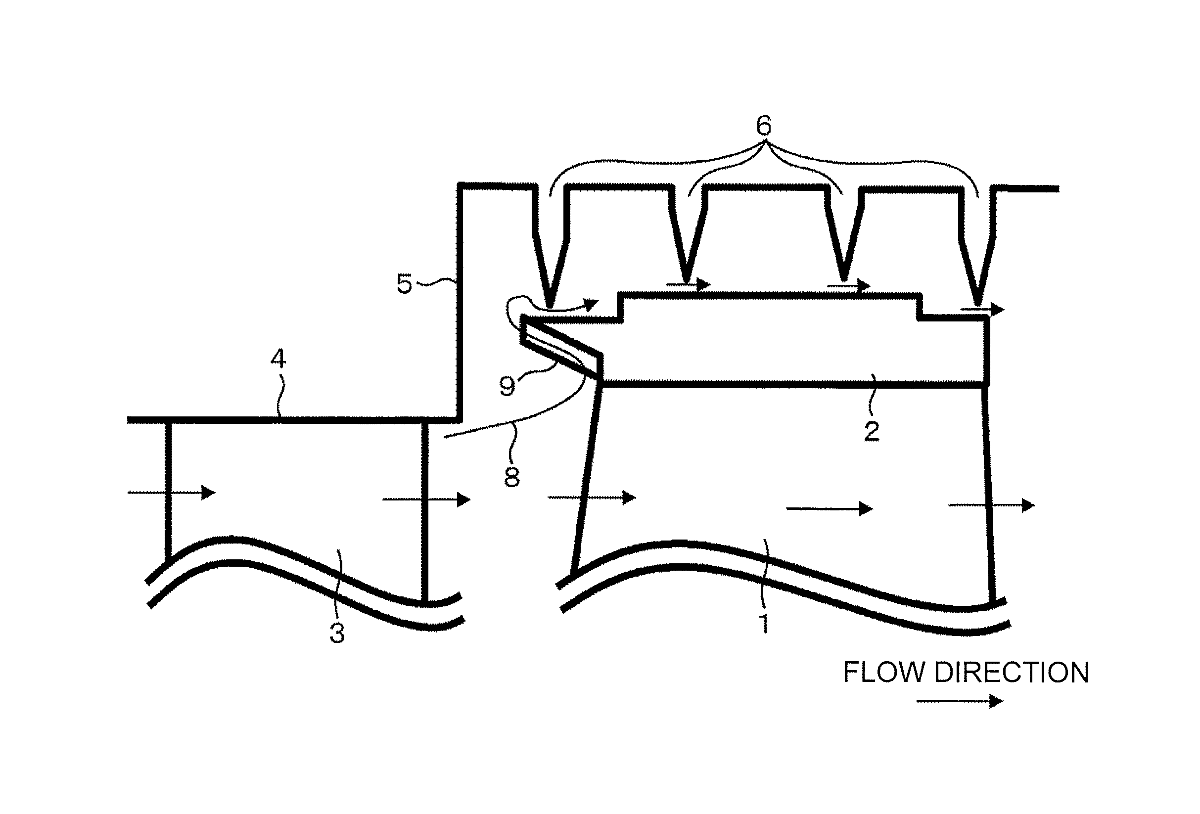
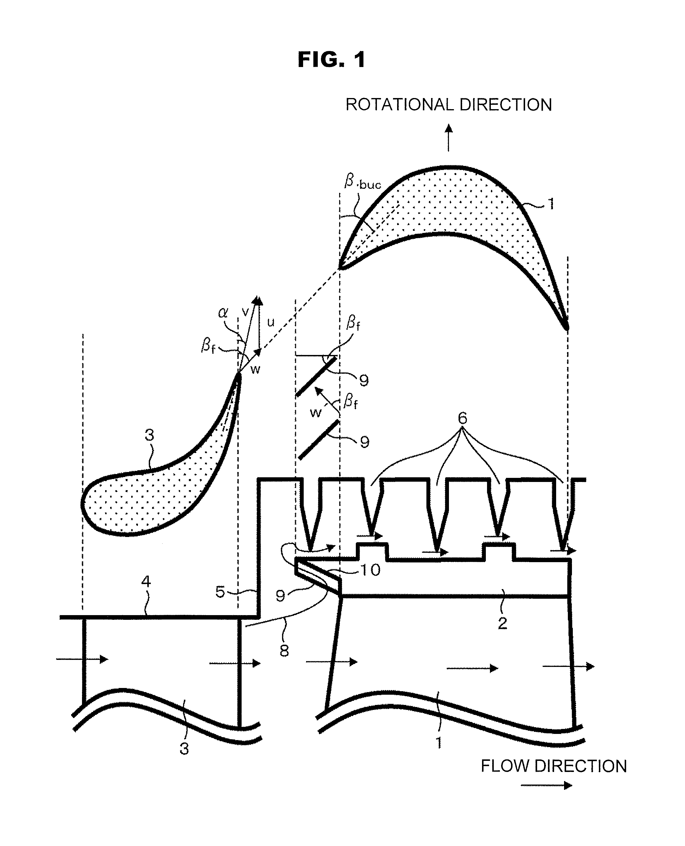
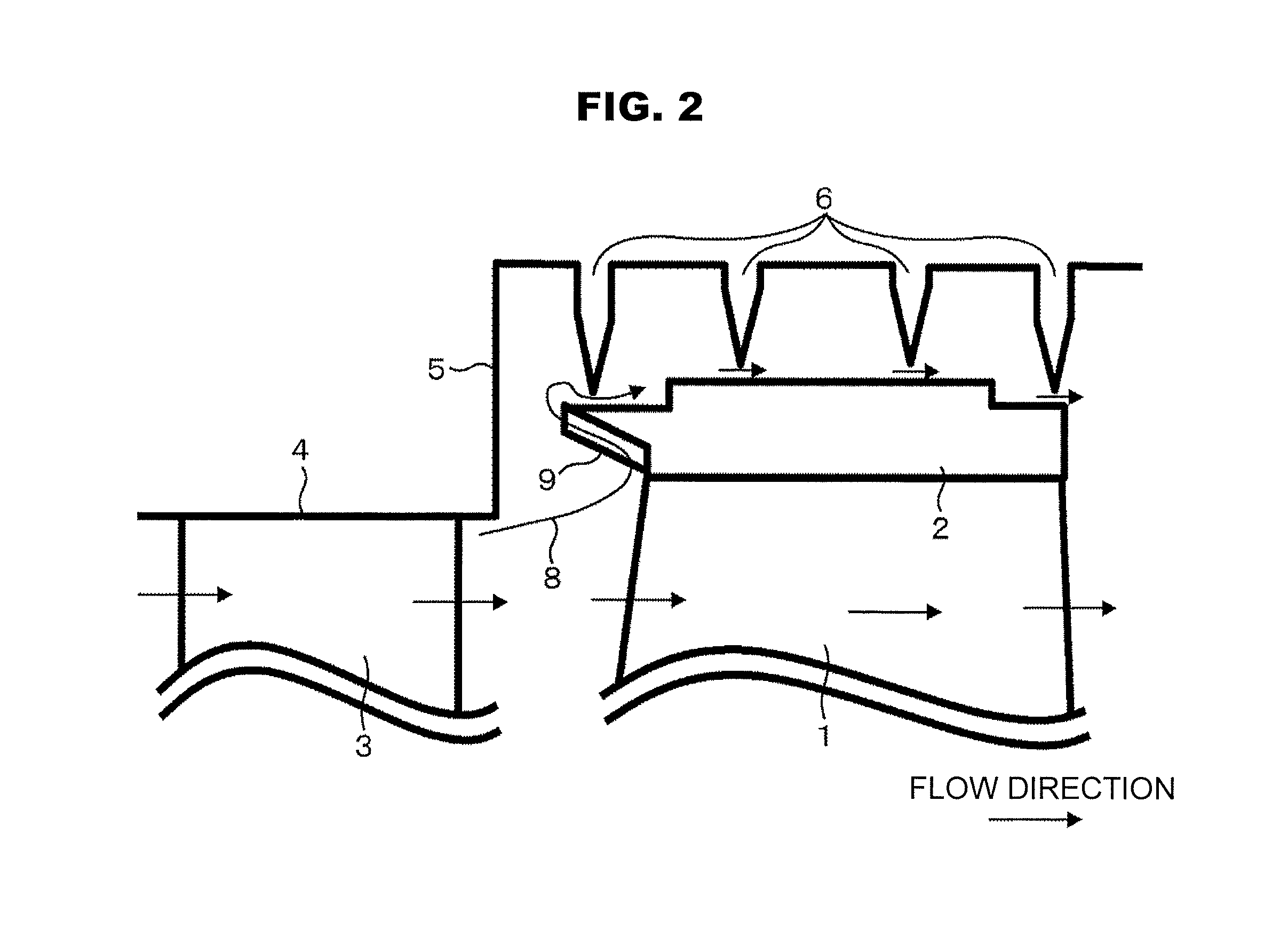
[0035]A first embodiment of the present invention will be described with reference to FIG. 1. FIG. 1 illustrates a structure of a turbine stage leakage portion as viewed from the radial direction (an upper view) and from the side (a lower view). In FIG. 1, there are shown a moving blade 1, a shroud cover 2, a stator vane 3, an outer circumferential side stationary wall 4, a vertical surface 5 of the outer circumferential side stationary wall, and labyrinth seal fins 6. In a steam turbine, the stator vanes 3 and the moving blades 1 are paired to form a turbine stage. A plurality of the stator vanes 3 are provided in the circumferential direction and their outer circumferential ends are supported by the outer circumferential side stationary wall 4 which is a stationary body. In contrast, a plurality of the moving blades 1 are secured to a turbine rotor not shown in the circumferential direction. The shroud cover 2 is provided on the outer circumferential side distal ends of the moving...

embodiment 2

[0045]A description is next given of a second embodiment of the present invention. FIG. 4 illustrates a structure of a turbine stage leakage portion as viewed from the side and FIG. 5 illustrates a structure of a whirl preventing groove 11 at a steam inlet side end portion of a shroud cover 2. Incidentally, constituent elements similar to those of the first embodiment are denoted with like reference numerals and their explanation is omitted.

[0046]The present embodiment differs from the first embodiment in that whirl preventing grooves 11 are characteristically provided at the steam inlet side end portion of the shroud cover 2 in place of the whirl preventing plate 9.

[0047]The whirl preventing grooves 11 radially passes through from the shroud cover inlet return portion 10 to the shroud outer circumferential surface. The whirl preventing grooves 11 as viewed from the axially upstream side are shown in FIG. 6A. The inner circumferential surface of the shroud cover return portion is ge...


PUM


Abstract

A rotor oscillation preventing structure for a steam turbine includes: a stator vane 3; a moving blade 1; a shroud cover 2 installed on an outer circumferential side distal end of the moving blade 1; and a plurality of seal fins 6 installed, at any interval in the axial direction of a rotor, on an wall surface of a stationary body located on an outer circumferential side of the shroud cover 2, a whirl preventing structure comprised of whirl preventing plates 9 or whirl preventing grooves 11 is provided at a shroud cover inlet return portion 10 of the shroud cover 2 so as to block the whirl flow of leakage flow 8 on an upstream side in an operating steam flow direction of the seal fins to reduce an absolute velocity component of the leakage flow 8 in a rotational direction of the rotor.

Description

BACKGROUND OF THE INVENTION[0001]1. Field of the Invention[0002]The present invention relates to a rotor oscillation preventing structure for a steam turbine.[0003]2. Description of the Related Art[0004]Steam turbines generally have a plurality of stages composed of moving blades and stator vanes in the axial direction of a turbine rotor as shown in FIG. 7. A gap exists between a moving blade and an outer circumferential side stationary wall and a portion of operating steam leaks through this gap. Leakage flow does not allow the moving flow to generate power; therefore, it results in a loss. In order to minimize the leakage, labyrinth seal fins are installed vertically to the axis of the turbine at the outer circumferential side stationary wall facing a shroud cover on the outer circumference of the moving blades. The labyrinth seal fins, along with the outer circumferential side stationary wall, form labyrinth seals.[0005]Incidentally, it is known that if the turbine rotor becomes ...

Claims


Application Information

Patent Timeline
Patent Type & Authority Patents(United States)
IPC IPC(8): F01D11/02
CPCF01D11/02F01D11/005F01D5/225
Inventor ONO, HIDEKIKUDO, TAKESHIMURATA, KENICHISONOBE, MASATAKASUGIYAMA, TSUTOMU
Owner MITSUBISHI POWER LTD
Learn More