Arrangement for controlling a track tension wheel of tracked vehicle

a technology for tension wheels and tracked vehicles, which is applied in mechanical devices, transportation and packaging, and equipment, etc., can solve the problems of not being able to produce an automatic extension, not being able to adapt to the needs of the user, and being easily damaged by extraneous damage, etc., to achieve automatic stabilization of the track tension, improve the control of the tension wheel, and improve the effect of running

Inactive Publication Date: 2014-04-29
BAE SYSTEMS HAGGLUNDS AKTIEBOLAG
View PDF9 Cites 1 Cited by
  • Summary
  • Abstract
  • Description
  • Claims
  • Application Information

AI Technical Summary

Benefits of technology

[0007]A primary object of the present invention is to propose a robust and compact arrangement of simple design for controlling a track tension wheel of a tracked vehicle, which will at the same time permit an improved control of the tension wheel in order to achieve modified running and emergency running characteristics on the ground surface and a substantially automatic stabilization of the track tension, irrespective of the actual height of the tension wheel relative to the ground surface, the tension wheel in moving between its upper and lower operating positions being made to move substantially vertically with a notional swivel axis situated far forward in the vehicle.
[0010]In a preferred embodiment of the arrangement the outer end of the linearly displaceable part of the second drive element is pivotally connected to a self-supporting arm part, which is rigidly connected to and laterally offset in relation to the two-armed lever carrying the wheel axle journal, and which is pivoted on the joint pin. Among other things, this affords an advantageous placement of the two drive elements, laterally offset in relation to one another.
[0011]The first guide arm and the second guide arm are suitably supported on a common swivel axis in the part fixed to the vehicle, which gives a compact construction.
[0012]In order to keep the first guide arm biased towards a lowered position of the tension wheel, the first guide arm is effectively connected to a torsion spring at the inner end of the first guide arm. The torsion spring is then preferably embodied as a torsion bar, which extends substantially parallel to the swivel axis of the first guide arm. The biasing of the first guide arm by the torsion spring means that, in the event of any loss of pressure in the second drive element, the tension wheel will be made to swivel upwards around the joint pin, which supports the two-armed lever, due to the fact that the opposite end of the two-armed lever to that supporting the tension wheel is pivotally connected to the third guide arm held fast by the first drive element. Adequate track tension can thereby be maintained, in order to afford the requisite emergency running characteristics of the vehicle in terms of steering and braking.

Problems solved by technology

This arrangement is not designed to be capable of producing an automatic extension of the drive track in the final phase of tension wheel lowering.
By virtue of its design construction the control arrangement for the tension wheel is bulky and can easily be exposed to damage from extraneous objects.
The control cylinder for swivelling the tension wheel arm upwards and downwards in this arrangement is furthermore firmly affixed to the vehicle, in such a way that it is incapable of allowing rapid suspension movements of the tension wheel arm, when the tension wheel runs over a raised object on the ground, for example.
This construction is relatively complicated, however, and costly to produce.

Method used


Image

  • Arrangement for controlling a track tension wheel of tracked vehicle
  • Arrangement for controlling a track tension wheel of tracked vehicle
  • Arrangement for controlling a track tension wheel of tracked vehicle

Examples


Embodiment Construction

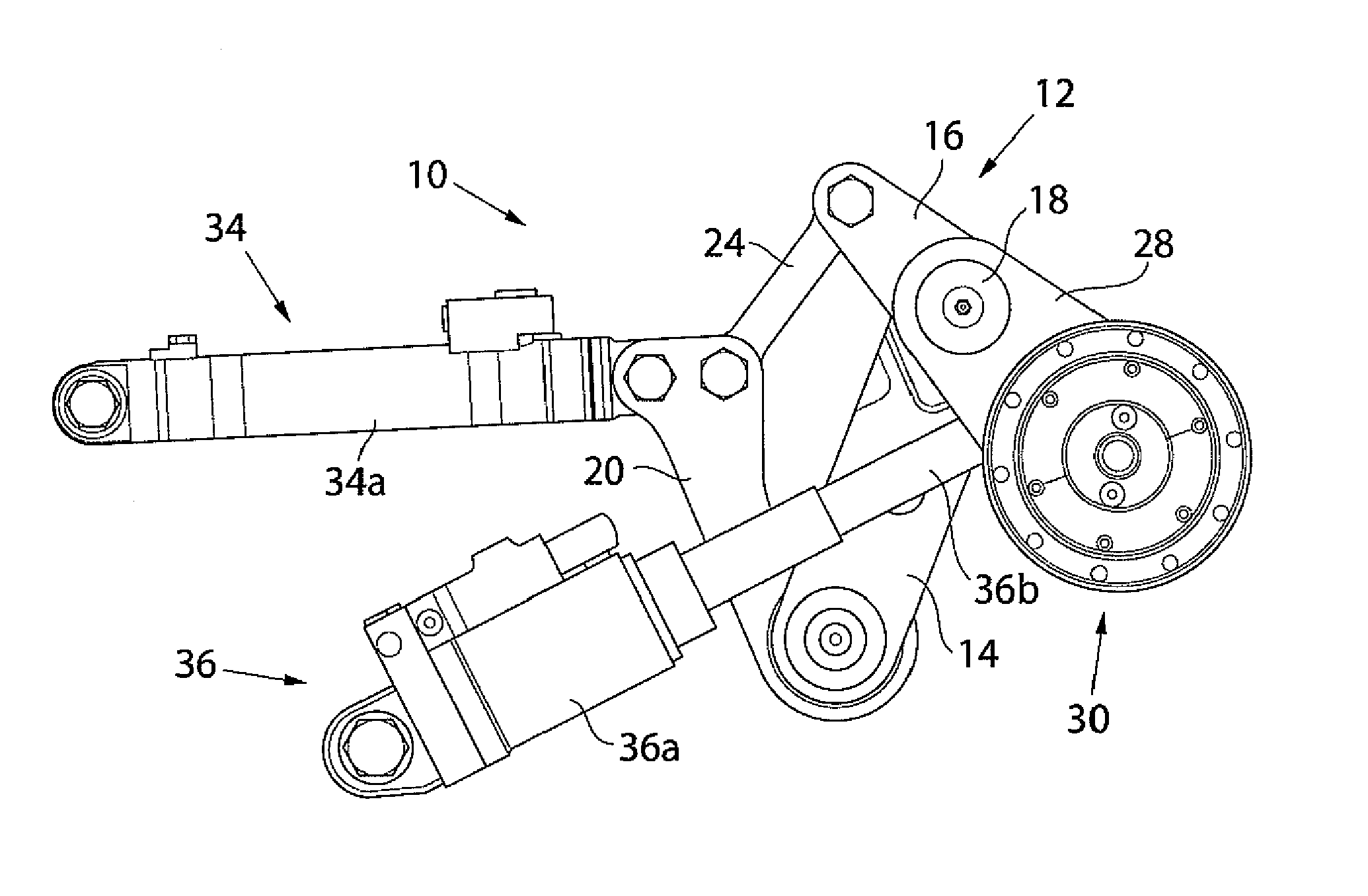
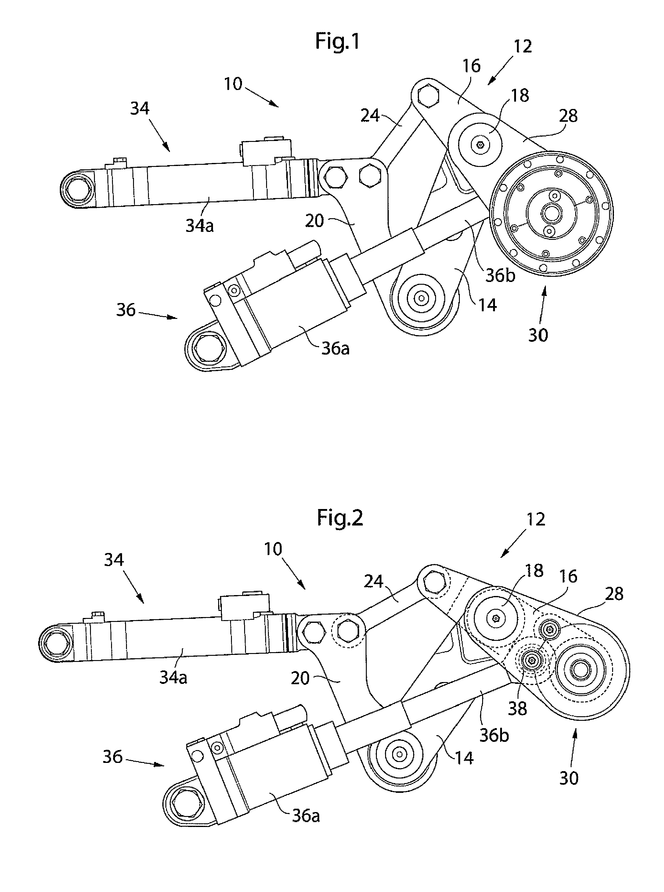
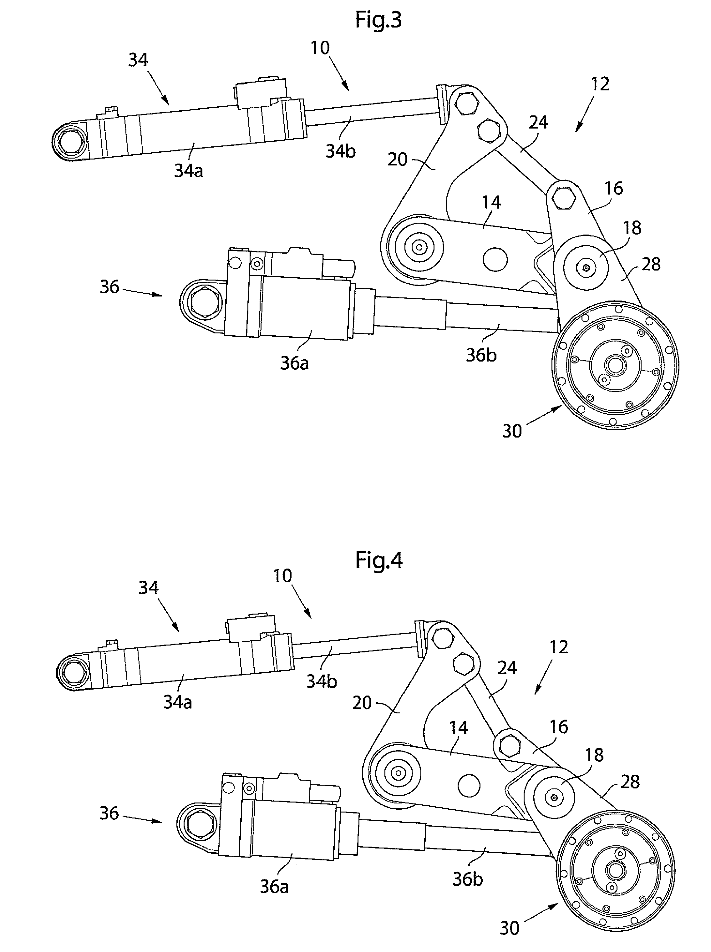
[0024]In the figures of the drawing a tension wheel control arrangement according to the invention is denoted overall by 10. The arrangement 10 has a guide arm system 12, which comprises a first guide arm 14, which at an inner end is swivel-mounted in a part (not shown) fixed to the vehicle and which at its outer end pivotally supports a two-armed lever 16 on a joint pin 18. The guide arm system 12 further comprises a second guide arm 20, which is swivel-mounted in the part fixed to the vehicle, preferably about the same swivel axis as the first guide arm 14. As is shown in more detail, particularly in FIGS. 5-7, the first guide arm 14 is formed as two parallel arm parts 14a, 14b connected by a body 22, between which arm parts the two-armed lever 16 is supported on the joint pin 18 and in which the second guide arm 20 is supported between the inner parts of the two connected arm parts 14a, 14b of the first guide arm 14. At its one, inner end a third guide arm 24 of the guide arm sys...


PUM


Abstract

Arrangement for controlling a track tension wheel of a tracked vehicle, comprising a guide arm system (12), which is swivel-mounted in a part fixed to the vehicle and which carries a wheel axle journal (29) for rotatably supporting the track tension wheel, in such a way that this can be swiveled by means of a first drive element (34) between a raised position and a lowered position, and a second drive element (36) for varying the center-to-center distance between the center axis of the track tension wheel and the swivel axis of the guide arm system in the part fixed to the vehicle. The guide arm system (12) comprises a first guide arm (14), which is swivel-mounted in the part fixed to the vehicle and which via a joint pin (18) pivotally supports a two-armed lever (16), a second guide arm (20), which is swivel-mounted in the part fixed to the vehicle and is pivotally connected to a linearly displaceable part (34b) of the first drive element (34), and a third guide arm (24), which is pivotally connected to the second guide arm (20) and is pivotally connected to the two-armed lever. One end of the lever (16) carries the wheel axle journal (29), while a linearly displaceable part (36b) of the second drive element (36) is effectively connected to the two-armed lever (16) carrying the wheel axle journal (29).

Description

CROSS REFERENCE TO RELATED APPLICATIONS[0001]This is a U.S. National Phase patent application of PCT / SE2009 / 051377, filed Dec. 4, 2009, which claims priority to Swedish Patent Application No. 0802581-9, filed Dec. 16, 2008, each of which is hereby incorporated by reference in the present disclosure in its entirety.TECHNICAL FIELD[0002]The invention relates to devices for controlling a track tension wheel of a tracked vehicle, and relates more specifically to an arrangement of the type which comprises a guide arm system, which at an inner part thereof is swivel-mounted in a part fixed to the vehicle and which on an outer part carries a wheel axle journal for rotatably supporting a hub of the track tension wheel, in such a way that this can be swivelled by means of a first drive element between a raised position and a lowered position, and a second drive element for varying the centre-to-centre distance between the centre axis of the track tension wheel and the swivel axis of the guid...

Claims


Application Information

Patent Timeline
Patent Type & Authority Patents(United States)
IPC IPC(8): B62D55/30
CPCB62D55/32B62D55/30B62D55/305
Inventor VIGREN, MATS
Owner BAE SYSTEMS HAGGLUNDS AKTIEBOLAG
Why Eureka
Try Eureka