Imaging terminal having focus control

a terminal and focus control technology, applied in the field of optical based registers, can solve the problems of long readout delay and processing delay, large image output times of terminals with variable focus position lens assemblies, and frustration of users of such terminals

Active Publication Date: 2014-04-08
HAND HELD PRODS
View PDF165 Cites 756 Cited by
  • Summary
  • Abstract
  • Description
  • Claims
  • Application Information

AI Technical Summary

Problems solved by technology

In spite of considerable advances in imaging technologies electronics, imaging terminals which are capable of capturing images continue to be plagued slow image output times which frustrate users of such terminals.
However, a high pixel count often leads to a longer readout delay and longer processing delay for processing image data corresponding to pixels of an image sensor pixel array.
However, like terminals with increased pixel resolution, terminals with variable focus position lens assemblies have been observed to exhibit considerable image output times.

Method used


Image

  • Imaging terminal having focus control
  • Imaging terminal having focus control
  • Imaging terminal having focus control

Examples


Embodiment Construction

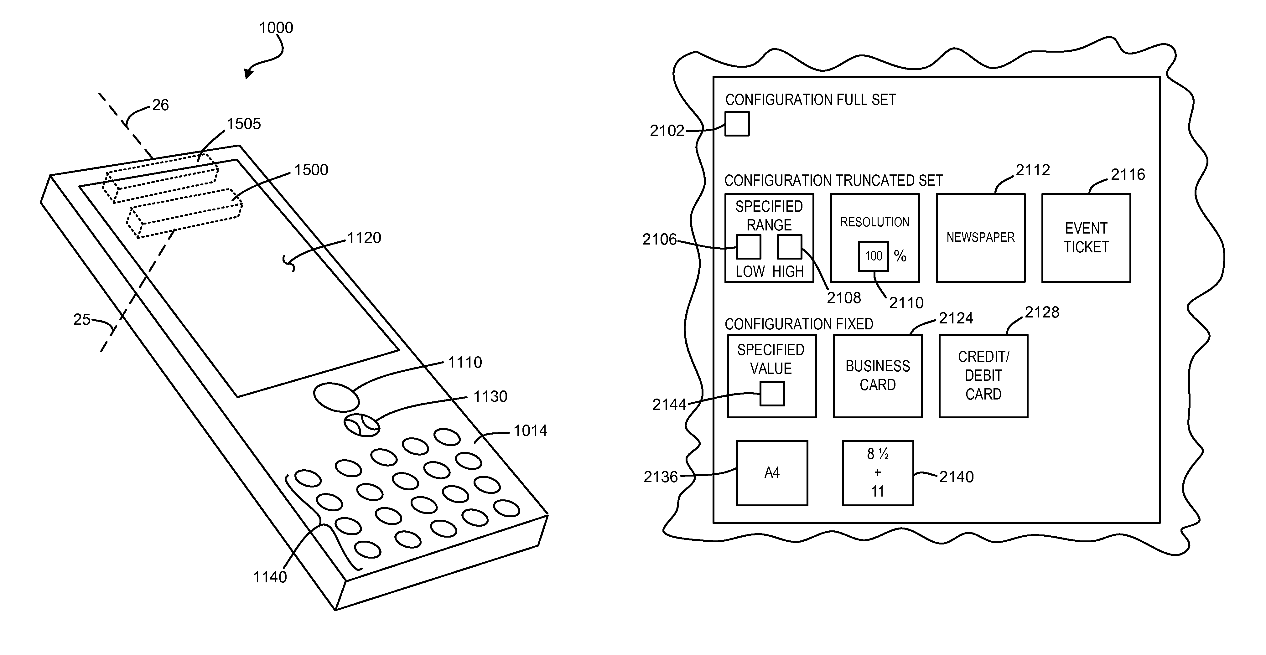
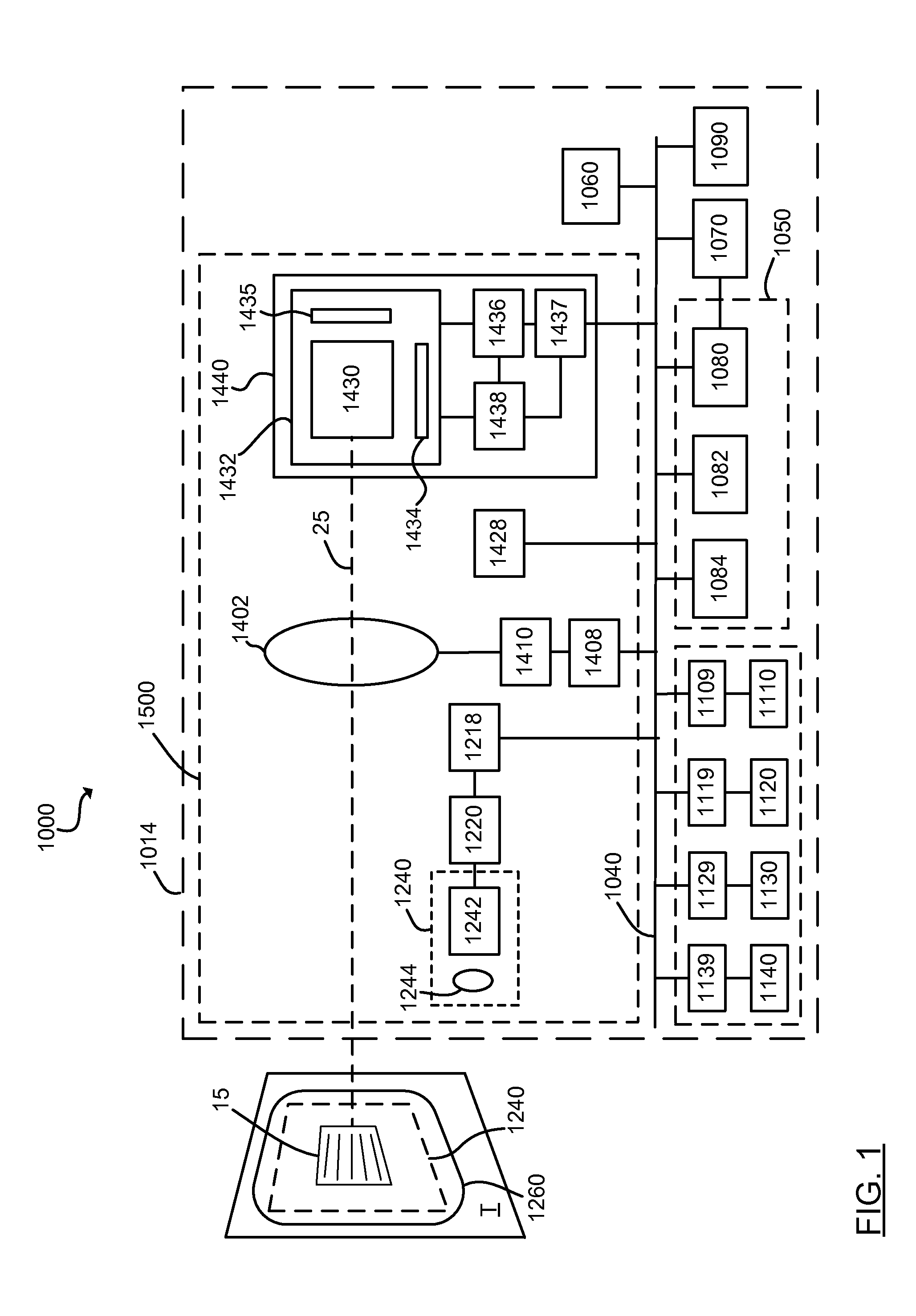
[0012]There is set forth herein an imaging terminal having an image sensor array and a variable lens assembly for focusing an image onto the image sensor array. In one embodiment, an imaging terminal can include one or more focusing configuration selected from the group comprising a full set focusing configuration, a truncated set focusing configuration and a fixed focusing configuration. When a full set focusing configuration is active, a full set of candidate focus settings can be active when the imaging terminal determines a focus setting of the terminal responsively to a trigger signal activation. When a truncated set focusing configuration is active, a truncated range of candidate focus settings can be active when the imaging terminal determines a focus setting of the terminal responsively to a trigger signal activation. When a fixed focusing configuration is active, the focus setting of the imaging lens assembly can be fixed so that a predetermined lens assembly focus setting ...


PUM


Abstract

There is set forth herein an imaging terminal having an image sensor array and a variable lens assembly for focusing an image onto the image sensor array. In one embodiment, an imaging terminal can include one or more focusing configuration selected from the group comprising a full set focusing configuration, a truncated set focusing configuration and a fixed focusing configuration. When a full set focusing configuration is active, a full set of candidate focus settings can be active when the imaging terminal determines a focus setting of the terminal responsively to a trigger signal activation. When a truncated set focusing configuration is active, a truncated range of candidate focus settings can be active when the imaging terminal determines a focus setting of the terminal responsively to a trigger signal activation. When a fixed focusing configuration is active, the focus setting of the imaging lens assembly can be fixed so that a predetermined lens assembly focus setting is active when a trigger signal is active.

Description

FIELD OF THE INVENTION[0001]The present invention relates in general to optical based registers, and particularly is related to an image sensor based imaging terminal.BACKGROUND OF THE INVENTION[0002]In spite of considerable advances in imaging technologies electronics, imaging terminals which are capable of capturing images continue to be plagued slow image output times which frustrate users of such terminals. Advances in imaging technology have actually been observed in some instances to increase rather than decrease an observed image output time of an imaging. One example is increased pixel resolution. Image sensors are being made available with ever increasing pixel resolution. Megapixel imagers are now commonplace. However, a high pixel count often leads to a longer readout delay and longer processing delay for processing image data corresponding to pixels of an image sensor pixel array. Imaging optics technologies have also improved. Imaging lens assemblies are available with ...

Claims


Application Information

Patent Timeline
Patent Type & Authority Patents(United States)
IPC IPC(8): G06F3/048H04N5/225H04N5/222G03B13/00
CPCH04N5/23212G06K7/10811G03B13/36G06K2207/1017G06K2207/1013H04N23/67
Inventor PEASE, MICHAELGARMON, SCOTTBAKER, JEFFREY
Owner HAND HELD PRODS
Why Eureka
Try Eureka