
Cart accessory handle for lifting and dumping

a technology for accessories and carts, applied in the direction of hand cart accessories, children carriages/perambulators, vehicles, etc., can solve the problems of spitting in the vicinity, difficult for a second groom to help lift and dump contents, etc., to save time and improve user safety.

Inactive Publication Date: 2014-04-01
STABLE INNOVATIONS
View PDF125 Cites 5 Cited by
  • Summary
  • Abstract
  • Description
  • Claims
  • Application Information

AI Technical Summary

Benefits of technology

The auxiliary handle enables two-person operation with equal lifting forces, enhancing user safety and preventing slipping or falling, allowing for efficient and ergonomic lifting and dumping of heavy loads into raised receptacles like dumpsters.

Problems solved by technology

The alternative is to use a fork to transfer portions of the cart contents over the edge of the dumpster thereby almost surely spilling some in the vicinity.
Since a stable cart or wheelbarrow is heavy and has a handle or handles on only one end of the bin for pushing, it is difficult for a second groom to help lift and dump the contents.

Method used


Image

  • Cart accessory handle for lifting and dumping
  • Cart accessory handle for lifting and dumping
  • Cart accessory handle for lifting and dumping

Examples


second embodiment

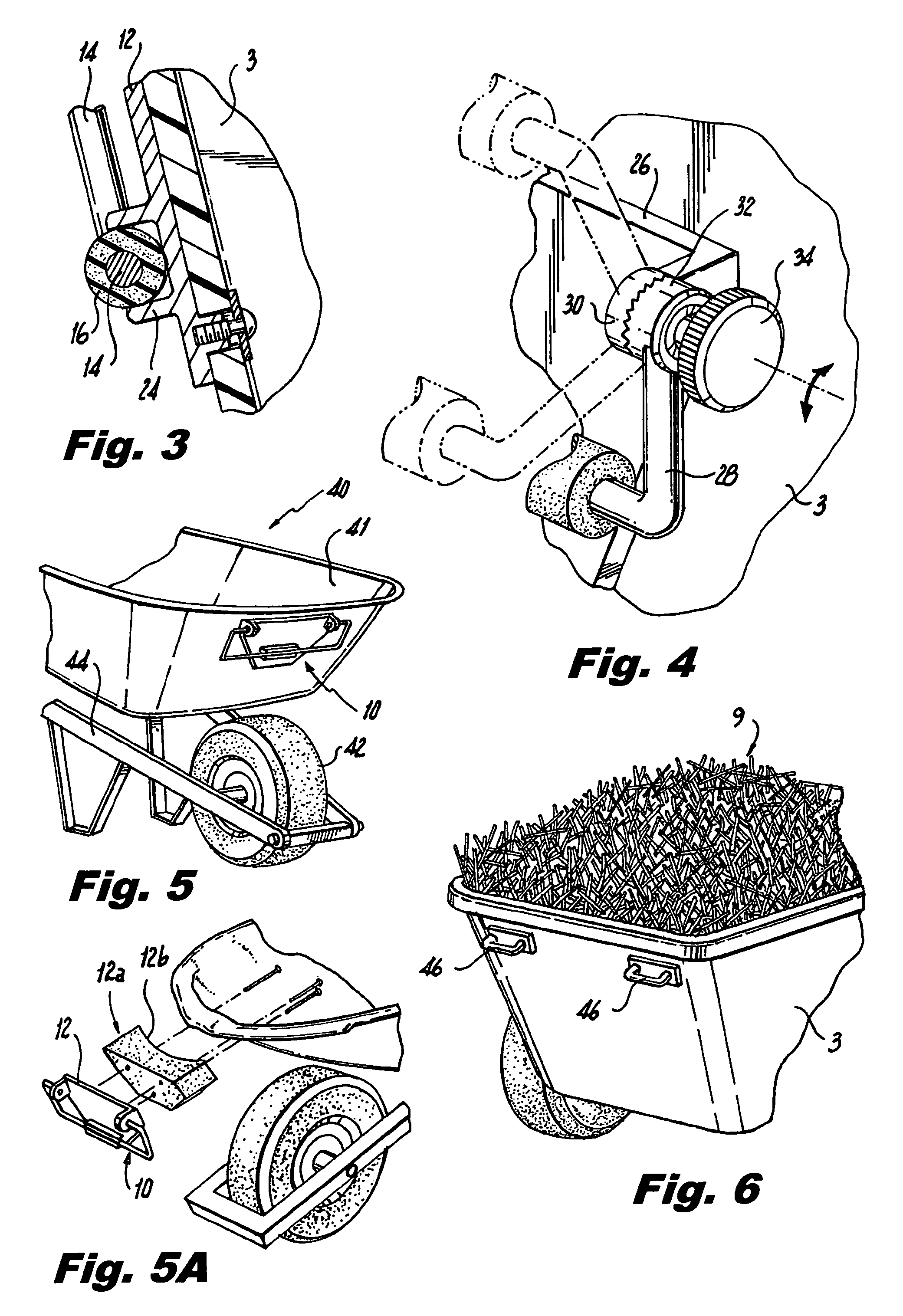
[0023]FIG. 4 shows the details of a second embodiment accessory front handle assembly. Frame 26 is rigidly attached to fixed ratchet member 30 while handle 28 is rigidly attached (as by welding, for example) to rotatable ratchet 32. Screw knob 34 forces the ratchet faces together to lock the position of handle 28 in any desired position as indicated by the two phantom views. This is ergonomically superior to handle 10 assembly as it affords rigidity to a handle 28 during the lifting and dumping procedure. The ratchet assembly 32 includes a fixed ratchet member 30 mounted on one of said forwardly extending members 28 of the bracket, a mating, rotatable ratchet member 32 attached to the corresponding end arm of the adjustable handle, and a screw knob 34 to separate the fixed and rotatable ratchet members 30, 32 temporarily to allow the resilient grip 16 to be positioned at any one of multiple positions between the parked position and the fully deployed position, whereby the elongated ...

third embodiment

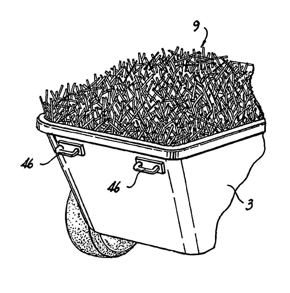
[0024]FIG. 6 shows accessory handle in which two separate short handles 46 substitute for a single centrally located handle. The separation of handles 46 afford good torque transfer to bin 3 for dumping.

[0025]FIG. 7 illustrates the equal height of the rear pushing handle and the grip 16 of handle assembly 10 when handle is at deployed height. It is this equal height at the level close to the top of bin 3 that is most useful for lifting and dumping. FIG. 7 also illustrates the equal height of the rear pushing handle 5 and the grip 16 of handle assembly 10 when the handle is at its deployed height. It is this equal height at the level close to the top of bin 3 that is most useful for lifting and dumping. This height also enables the users, such as two grooms at a racetrack, to have the respective handles 5 and 10 at equal chest height when the biceps are strongest at an ergonomic right angle, when tipping the contents 9 of the cart 1 into a dumpster 53. If the handles 5 and 10 were mu...


PUM


Abstract

A dual handled liftable wheelbarrow with a bin and a wheel assembly has a fixed handle mounted on a rear wall thereof. A bracket is mounted on an outside of the front wall for mounting an adjustable handle with an elongated resilient grip having end arms swiveling about and mounted on said forwardly extending members of the bracket, so that the handle is rotatable between a parked position flush downwardly against the outside of said front wall, and an upwardly extending deployed position with said resilient grip above the open top of said bin. The fixed and adjustable handles are mounted at substantially equal heights on the rear and front walls, respectively, of the bin to allow two users working together to unload debris from the bin over a side wall of the bin into a collection box.

Description

FIELD OF THE INVENTION[0001]The present invention relates to accessory handles for lifting wheelbarrows and carts.BACKGROUND OF THE INVENTION[0002]Carts and wheelbarrows are well represented in the prior art. Some carts are general purpose, while others are designed for a specific use. Wheelbarrows are used commonly both on the farm as well as the construction site. A stable for the use of horses requires frequent cleaning and moving of used straw from the stalls to a dumping area which can be a dumpster with high sides. Carts with two wheels and a deep bin are often used. Wheelbarrows with one wheel are also used at times for the same purpose to move the used straw. Since the carts and wheelbarrows for stall cleaning service must be emptied in an efficient manner, an auxiliary handle mounted to the bin portion opposite the primary handle or handles is an effective aid in this task.[0003]U.S. Pat. No. 2,350,062 of Mosier shows a four wheel cart with small wheels, a low bin portion, ...

Claims


Application Information

Patent Timeline
Patent Type & Authority Patents(United States)
IPC IPC(8): B62B1/18B62B1/20
CPCB62B5/061B62B1/204B62B5/067B62B1/22B62B1/20B62B1/18B62B5/064
Inventor SKIJUS, JOHNBERINATO, THOMAS
Owner STABLE INNOVATIONS
Learn More