Operation input unit and manipulator system

a technology of which is applied in the field of operation input unit and manipulator system, can solve the problems of mismatching the manipulating direction of the operating unit, the wearer is unable to operate the operating unit, and the vertical and lateral directions of the device or the like can be manipulated on the hmd, so as to prevent unintended movement

Active Publication Date: 2014-03-25
OLYMPUS CORP
View PDF20 Cites 3 Cited by
  • Summary
  • Abstract
  • Description
  • Claims
  • Application Information

AI Technical Summary

Benefits of technology

[0007]It is an object of the present invention to provide an operation input unit and a manipulator system capable of rapidly detecting a state in which an operator becomes unable to normally operate the operating unit and capable of preventing unintended motion of a displayed object.

Problems solved by technology

When a wearer manipulates a displayed object, such as a device, displayed on the HMD with an operating unit in his or her hand, it sometimes becomes impossible for the wearer to operate the operating unit because the wearer suddenly changes his or her posture or releases the operating unit for some reason.
Furthermore, when a wearer manipulates the operating unit in an orientation inclined toward the operating unit due to carelessness or the like, the vertical and lateral directions of the device or the like to be manipulated on the HMD and the manipulating direction of the operating unit sometimes become mismatched.

Method used


Image

  • Operation input unit and manipulator system
  • Operation input unit and manipulator system
  • Operation input unit and manipulator system

Examples


first embodiment

[0022]An operation input unit 1 and a manipulator system 100 according to the present invention will be described below with reference to FIGS. 1 to 8.

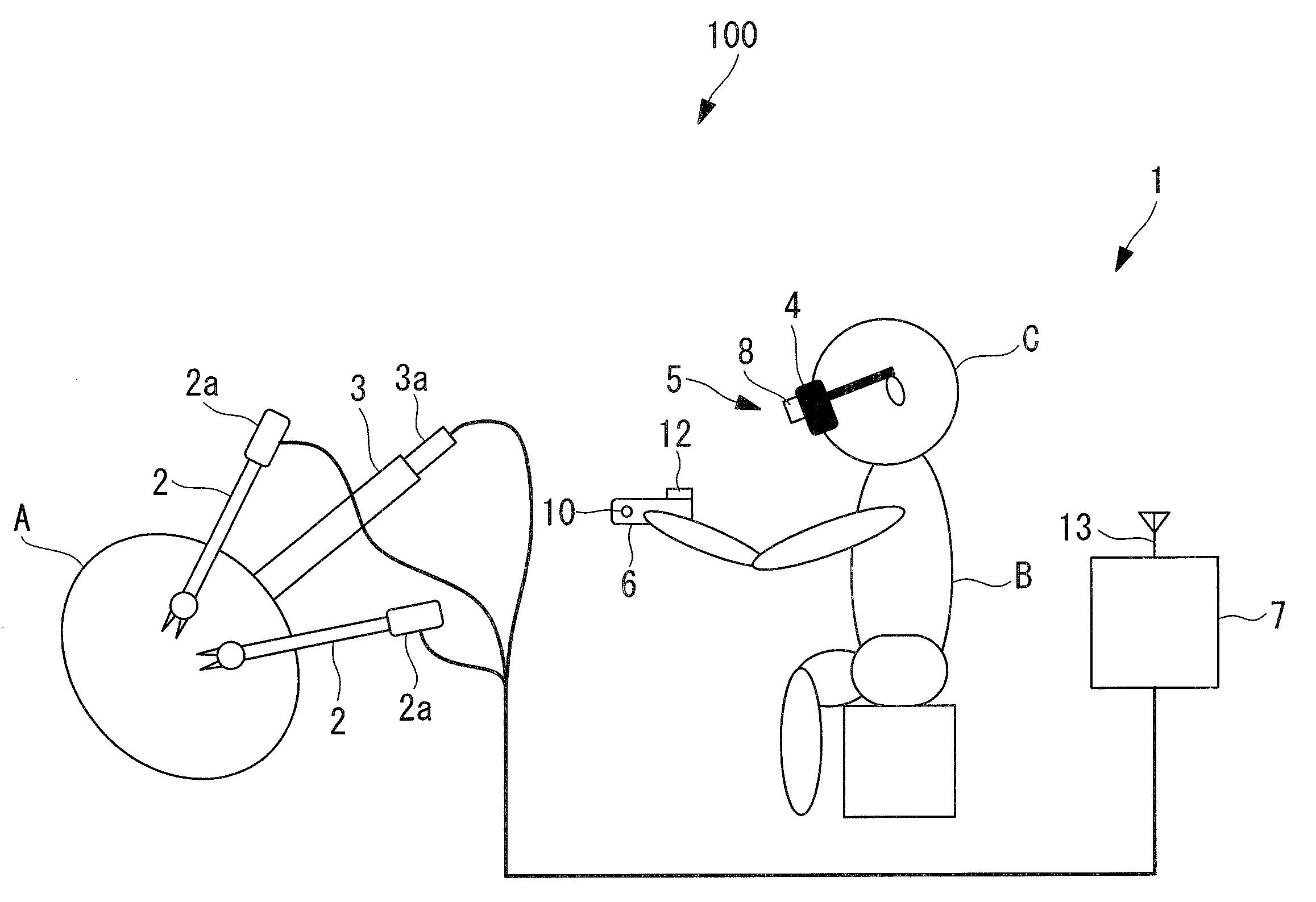
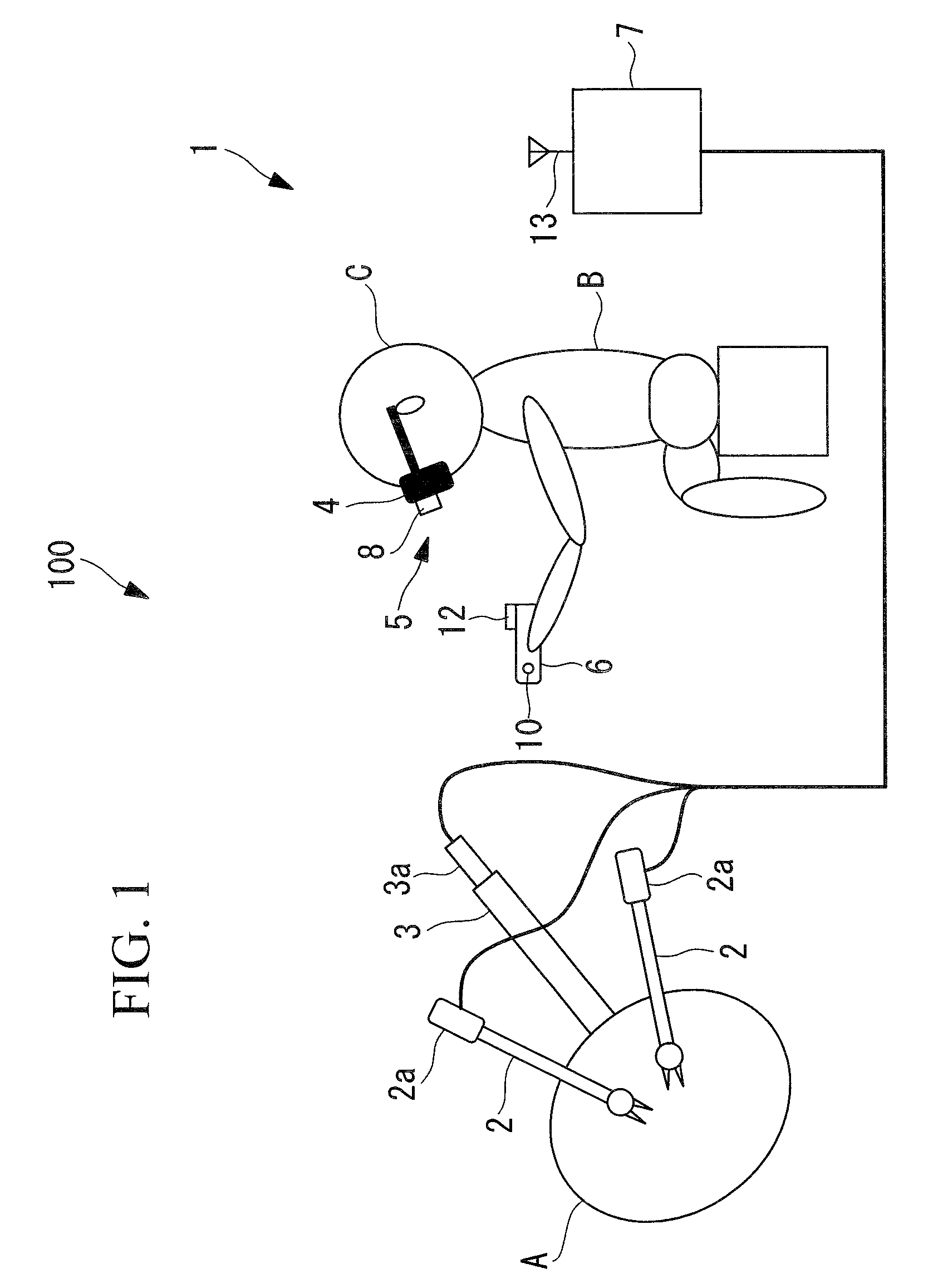
[0023]The manipulator system 100 according to this embodiment is used for surgical procedures. As shown in FIG. 1, the manipulator system 100 includes a manipulator (displayed object) 2 to be inserted into the body of a patient A, an endoscope (observation unit) 3 that acquires an image of the manipulator 2, and the operation input unit 1 according to this embodiment.

[0024]The manipulator 2 can be changed in orientation, position, and operating state with a motor 2a. The endoscope 3 can be changed in orientation, position, and operating state with a motor 3a.

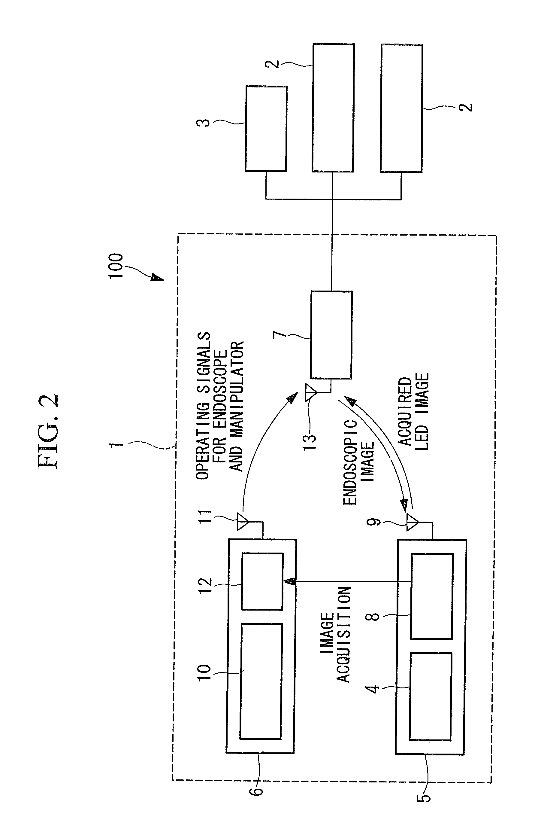
[0025]The operation input unit 1 is equipped with a HMD (head-mounted unit) 5 having a display section 4 (display) and mounted on the head C of an operator B, an operating unit 6 operated by the operator B, and a control unit 7 that moves the manipulator 2 based on the operation ...

second embodiment

[0050]Next, an operation input unit 1 and a manipulator system 100 according to the present invention will be described below with reference to FIGS. 9 and 10.

[0051]In this embodiment, differences from the first embodiment will be mainly described, and configurations common to the first embodiment are given the same reference numerals, and descriptions thereof will be omitted.

[0052]As shown in FIG. 9, the operation input unit 1 according to this embodiment differs from the first embodiment in that it is equipped with acceleration sensors (relative-position detecting sections) 14 and 24 and contact sensors 15 and 25 provided at the HMD 5 and the operating unit 6, respectively, and a line-of-sight sensor 16 provided at the HMD 5.

[0053]The acceleration sensors 14 and 24 detect accelerations in three different directions.

[0054]The contact sensor 15 provided at the HMD 5 is disposed at a position at which it comes into contact with the head C of the operator B when the operator B wears t...


PUM


Abstract

Unintended motion of a displayed object is prevented by rapidly detecting a state in which an operator becomes unable to operate an operating unit. Provided is an operation input unit including a display; a head-mounted unit; an operating unit to which an operating signal for a displayed object displayed on the display is input; a relative-position detecting section that detects the relative position between the head-mounted unit and the operating unit; and a control unit that controls the displayed object by switching between a first control mode in which the motion of the displayed object is controlled in accordance with an operating signal input to the operating unit and a second control mode in which the motion of the displayed object is controlled by limiting an operating signal input to the operating unit on the basis of the relative position detected by the relative-position detecting section.

Description

BACKGROUND OF THE INVENTION[0001]1. Field of the Invention[0002]The present invention relates to an operation input unit and a manipulator system.[0003]This application is based on Japanese Patent Application No. 2010-075378, the content of which is incorporated herein by reference.[0004]2. Description of Related Art[0005]Known head mounted displays (HMD) clear the field of view of wearers whose views are obstructed or notify the wearers of an abnormality when an outside abnormality is detected (for example, refer to Japanese Unexamined Patent Application, Publication No. Hei 5-304646 and Japanese Unexamined Patent Application, Publication No. Hei 9-149339).[0006]When a wearer manipulates a displayed object, such as a device, displayed on the HMD with an operating unit in his or her hand, it sometimes becomes impossible for the wearer to operate the operating unit because the wearer suddenly changes his or her posture or releases the operating unit for some reason. Furthermore, when...

Claims


Application Information

Patent Timeline
Patent Type & Authority Patents(United States)
IPC IPC(8): G09G5/00A61B1/00
CPCA61B1/00039A61B1/00131A61B1/00042
Inventor OGAWA, RYOHEIKISHI, KOSUKE
Owner OLYMPUS CORP
Why Eureka
Try Eureka