
Cryosurgical device with metered dose

a cryosurgical device and metered dose technology, applied in the field of cryosurgical devices, can solve the problems of destroying cells, freezing blood vessels supplying abnormal cells with blood, and uncontrolled amount of coolant solution being dispensed from the container into the supply tube, so as to facilitate multiple freeze and thaw cycles, effectively view and assess the treatment area

Active Publication Date: 2014-03-18
3JT ENTERPRISES
View PDF25 Cites 152 Cited by
  • Summary
  • Abstract
  • Description
  • Claims
  • Application Information

AI Technical Summary

Benefits of technology

[0014]Accordingly, it is a benefit of the present invention to provide a cryosurgical device and system for cryosurgically treating skin disease and a method of using such a device and system that provides for the effective treatment of abnormal tissue.
[0015]It is further benefit of the present invention to provide a cryosurgical device and system for cryosurgically treating skin disease and a method of using such a device and system that does not waste the coolant solution used in connection with the device.
[0016]It is another benefit of the present invention to provide a cryosurgical device and system for cryosurgically treating skin disease and a method of using such a device and system to evenly distribute a controlled amount of coolant solution to a precisely demarcated area and to prevent spraying or splashing of the coolant solution onto undesired areas of the patient or practitioner.

Problems solved by technology

When extreme cold is applied to abnormal cells, ice crystals can form inside the cells, which can rupture their cell membranes, thus destroying the cells.
The extreme cold can also freeze blood vessels supplying blood to the abnormal cells.
In these methods, the coolant solution is typically stored in a pressurized container, and, upon demand, an uncontrolled amount of coolant solution is dispensed from the container into a supply tube.
First, the coolant solution is often wasted.
When an uncontrolled amount of coolant solution is dispensed from the container, a large portion of the coolant solution is wasted due to the uncontrolled dispensing from the container and what is called blowback by those of skill in the art.
When this happens, an excessive amount of coolant solution is released into the surrounding atmosphere rather than directed onto the abnormal tissue.
When a porous tip applicator is used to apply the coolant solution to abnormal tissue, an excessive amount of coolant solution is often delivered through the supply tube to saturate the applicator.
When this happens, coolant solution is dispensed directly into the atmosphere and thus, coolant solution is wasted.
Furthermore, not all of the coolant solution absorbed in or on the applicator reaches the abnormal tissue.
Additionally, the shapes of these applicators do not allow the coolant solution to be distributed evenly or onto a precisely demarcated area.
Another disadvantage of devices used in connection with the above-described methods is that the coolant solution is dispersed in an uncontrolled manner.

Method used


Image

  • Cryosurgical device with metered dose
  • Cryosurgical device with metered dose
  • Cryosurgical device with metered dose

Examples


first embodiment

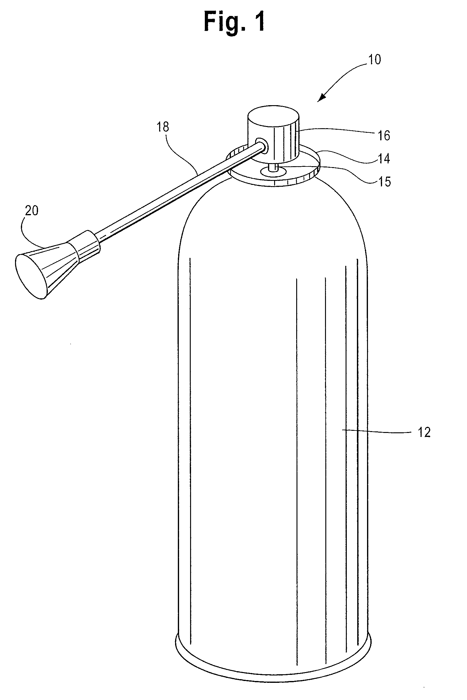
[0050]FIG. 1 illustrates a perspective view of a cryosurgical device 10 for use in a system in accordance with the present invention. As seen in FIG. 10, the cryosurgical device 10 can incorporate a container 12. The container 12 can be made of, for example, steel or aluminum, and can be used to safely hold a coolant solution, for example, a liquid cryogen. In embodiments of the claimed invention, the container 12 can be pressurized and can be, for example, an aerosol container.

[0051]The container 12 can contain a coolant solution that can be used in connection with cryosurgically treating skin diseases, for example, skin lesions. The coolant solution can be, for example, liquid nitrogen, or any solution known by those of skill in the art to be used in cryosurgery. In embodiments of the claimed invention, the coolant solution can be a mixture of 95% dimethyl ether (DME) and 5% propane or a mixture of 95% DME, 2% propane, and 3% isobutene. In alternate embodiments, the coolant soluti...

second embodiment

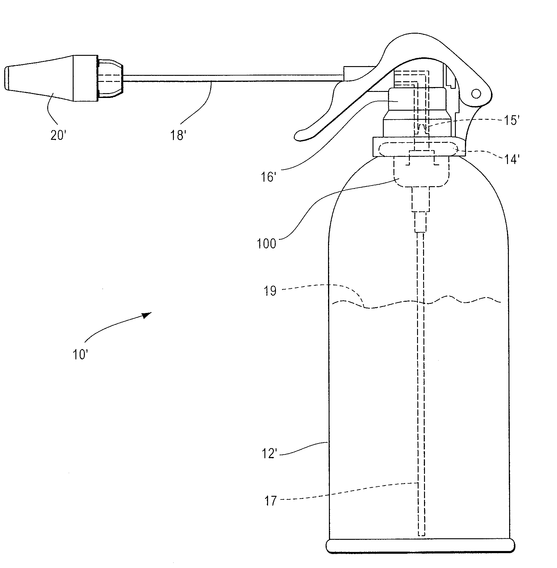
[0054]Referring to FIG. 10, a cross-sectional view of a cryosurgical device in accordance with the present invention is shown. Elements of the cryosurgical device 10′ are most clearly illustrated in FIG. 10 and are described in further detail.

[0055]A metered valve assembly 100 can be incorporated into the device. The metered valve assembly 100 includes a valve cup 14′, which seals the container and holds the metered valve. A dip tube 17 extends from the metered valve assembly 100 into the container 12′ and directs the coolant solution 19 from the container 12′ to the metered valve in the valve cup 14′.

[0056]When the actuator / trigger assembly 16′ is at rest, a chamber in the metered valve fills up thereby measuring a predetermined amount of coolant solution 19. When the actuator / trigger assembly 16′ is engaged, the coolant solution 19 is released from the chamber of the metered valve through the valve stem 15′, through the actuator / trigger assembly 16′, and into the applicator tube 1...


PUM


Abstract

A cryosurgical device and system is provided comprising a pressurized container, a metered valve that regulates the retrieval of a coolant solution stored in the pressurized container and regulates the volume of coolant solution dispensed with each actuation of the device, an actuator that engages the metered valve when engaged, and directs the coolant solution to an extension tube, which directs the coolant solution away from the pressurized container, and an applicator head configuring an open-ended enclosure attached to a distal end of the extension tube.

Description

FIELD OF THE INVENTION[0001]The present invention relates generally to the field of cryosurgical devices for cryosurgically treating skin diseases and more particularly to a cryosurgical device for applying a cryogenic refrigerant from a pressurized container in metered doses.BACKGROUND OF THE INVENTION[0002]Cryosurgery is the application of extreme cold to destroy abnormal or diseased tissue and can be used to treat a number of skin diseases and disorders. Cryosurgery is generally employed in the medical field for the removal of skin lesions from the body of a mammal, including the human body. When extreme cold is applied to abnormal cells, ice crystals can form inside the cells, which can rupture their cell membranes, thus destroying the cells. The extreme cold can also freeze blood vessels supplying blood to the abnormal cells.[0003]Traditionally, liquid nitrogen has been used as the coolant solution in cryosurgery. However, other coolant solutions have been used and are known by...

Claims


Application Information

Patent Timeline
Patent Type & Authority Patents(United States)
IPC IPC(8): A61B18/02
CPCB65D83/201A61B18/0218B65D83/20B65D83/303B65D83/54
Inventor GOLDBOSS, ANTHONYINCORVIA, CHARLESGOLDBOSS, JUDY
Owner 3JT ENTERPRISES
Learn More