
Hydraulic brake apparatus of motorcycle

a technology of hydraulic brakes and motorcycles, which is applied in the direction of braking systems, cycle equipment, cycle equipment, etc., can solve the problems of reducing the service life of the brake apparatus, so as to reduce the length of the brake fluid pipe, and reduce the effect of equipment removal

Active Publication Date: 2014-03-18
KAWASAKI MOTORS LTD
View PDF19 Cites 5 Cited by
  • Summary
  • Abstract
  • Description
  • Claims
  • Application Information

AI Technical Summary

Benefits of technology

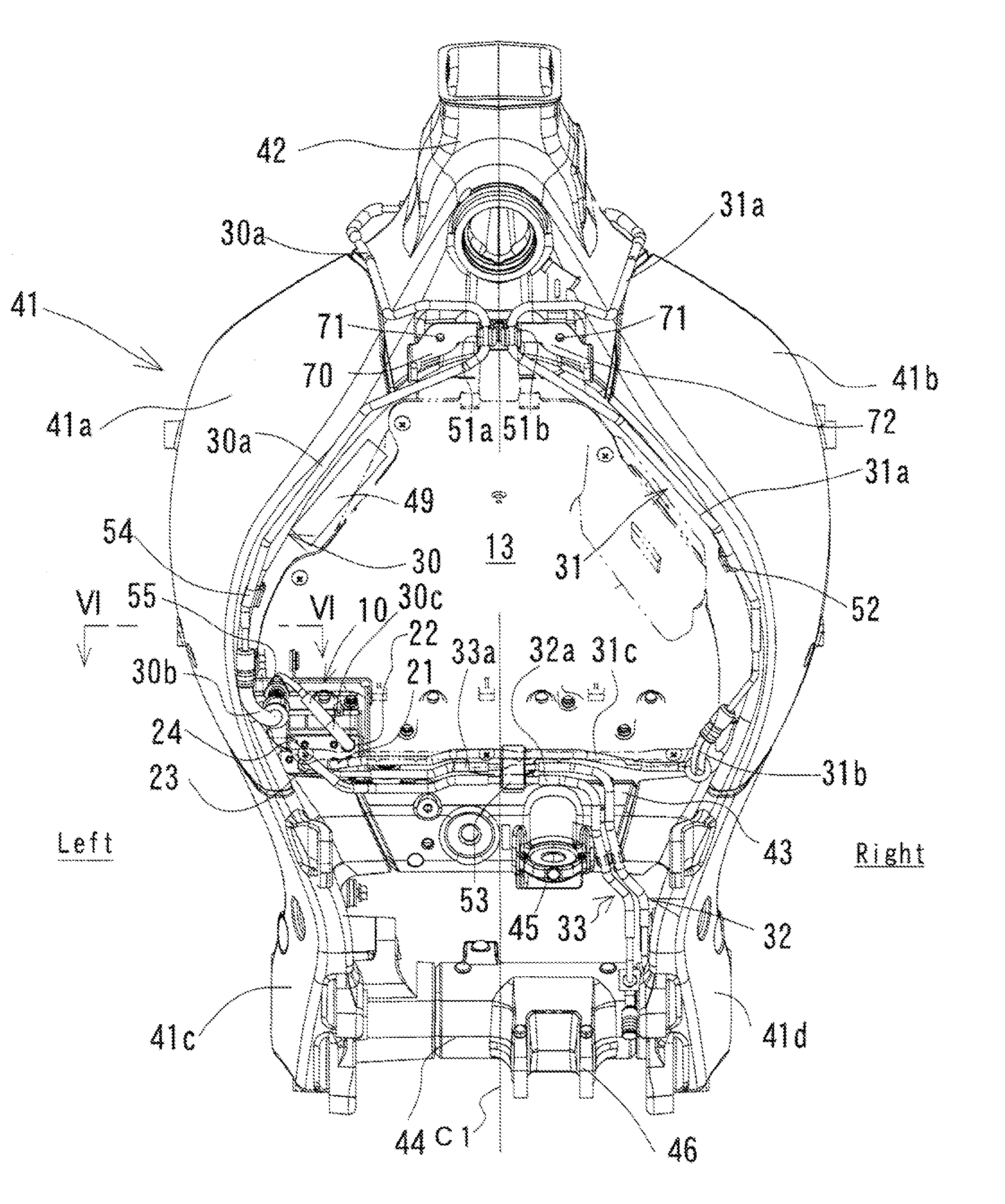
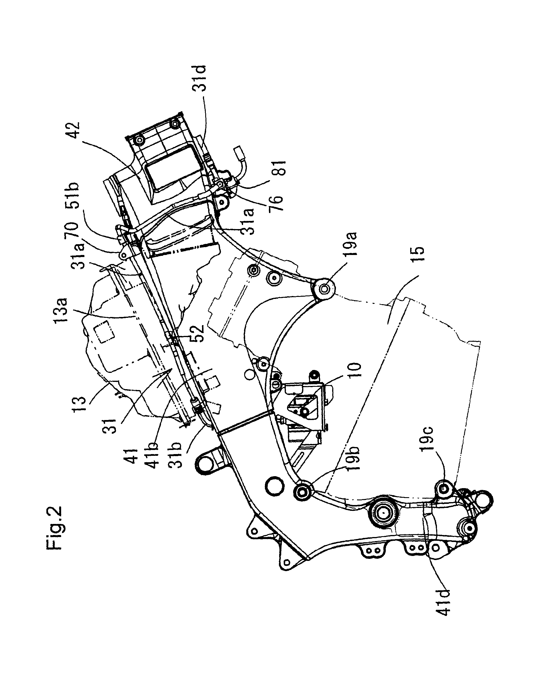
[0013](1) According to the present invention, the brake fluid pipe is arranged along the upper surface of the frame member, so that it can be arranged compactly, and can largely secure the space between the right and left frame members, whereby the shape of the equipment arranged between the right and left frame members can be large, and the detaching of the equipment can be easy. In addition, the maintenance of the brake fluid pipe itself can be easy.
[0014](2) With the configuration (a), the brake lever brake fluid pipe and the caliper brake fluid pipe for braking the front wheel are provided on the upper surfaces of the frame members, so that the piping length of the brake fluid pipes can be shortened, and a layout placement of the brake fluid pipes can be simplified. When both the brake fluid pipes are distributively arranged on the right and left frame members, the small spaces above the right and left frame members can be used effectively, respectively. On the other hand, when both the brake fluid pipes are arranged together on one of the right and left frame members, the number of components such as clamp members for attaching can be reduced, and the attaching operation of the brake fluid pipe can be easy.
[0015](3) With the configuration (b), in the brake fluid pipe, one end portion in the froe-aft direction is formed of a member having flexibility, and a remaining portion is formed of a member having higher rigidity than the one end portion. Accordingly, when the equipment is detached, the one end portion having flexibility is used to extend the brake fluid pipe outward in the right and left direction, so that the detaching of the equipment can be easy.
[0016](4) With the configuration (c), a clamp fixing the brake fluid pipe is provided in the upper portion of the frame member, so that the equipment arranging space between the right and left frame members can be secured more largely.
[0017](5) With the configuration (d), the hydraulic control unit and the front wheel caliper brake fluid pipe are arranged so as to be displaced to the same side of the right and left sides, so that the distance between the hydraulic control unit and the front wheel caliper can be shortened to shorten a piping path.

Problems solved by technology

However, when the brake fluid pipes are arranged on the inner side surfaces of the frame members, the space between the right and left frame members becomes smaller to limit the size of the equipment arranged between the frame members.
For example, when the air cleaner box is arranged between the frame members, its volume is limited to affect air intake performance or air intake noise.
Further, when the equipment such as the air cleaner box is detached, the brake fluid pipes interfere with the equipment, with the result that the detaching operability is low.

Method used


Image

  • Hydraulic brake apparatus of motorcycle
  • Hydraulic brake apparatus of motorcycle
  • Hydraulic brake apparatus of motorcycle

Examples


first embodiment

(The Overview of Piping for Hydraulic Brake Apparatus)

[0029]FIGS. 1 to 10 show a motorcycle including a hydraulic brake apparatus according to a first embodiment of the present invention. First, the overview of the hydraulic brake apparatus will be described with reference to a brake piping diagram shown in FIG. 3. In FIG. 3, the hydraulic brake apparatus includes, as a brake operating portion, a front wheel brake lever 1 provided on a steering handlebar, and a rear wheel brake pedal 2 provided near a right step. The brake lever 1 and the brake pedal 2 are connected to master cylinders 3 and 4, respectively. The hydraulic brake apparatus includes, as a wheel braking portion, a pair of right and left front wheel disc braking devices 7 provided on a front wheel 5, and a rear wheel disc braking device 8 provided on a rear wheel 6. The disc braking devices 7 and 8 are provided with calipers 7a and 8a for sandwichably pressing the brake discs, respectively. In this embodiment, a hydrauli...


PUM


Abstract

An hydraulic brake apparatus of a motorcycle, including a main frame having a pair of right and left frame members extending rearward from a head pipe, and equipment arranged in a space between the right and left frame members. The hydraulic brake apparatus further includes at least one brake fluid pipe, wherein the at least one brake fluid pipe is arranged so as to extend rearward from near the head pipe along an upper surface at least one of the frame members.

Description

FIELD OF THE INVENTION[0001]The present invention relates to a hydraulic brake apparatus of a motorcycle, which includes a main frame having a pair of right and left frame members extending rearward from a head pipe, and equipment arranged in a space between the right and left frame members.DESCRIPTION OF THE RELATED ART[0002]In a brake piping configuration of the hydraulic brake apparatus, typically, a brake lever on a steering handlebar and a brake pedal provided near a step are connected to braking portions such as disc brakes arranged on front and rear wheels via various brake fluid pipes (Japanese Patent Application Publication (JP-B) No. 7-88158). For the characteristic of a motorcycle required to have compactness, the brake fluid pipes are required to be disposed so as to be hard to see from the outside as much as possible and so as not to obstruct the arrangement of various equipment.[0003]In addition, as a configuration of a main frame of a motorcycle, right and left frame ...

Claims


Application Information

Patent Timeline
Patent Type & Authority Patents(United States)
IPC IPC(8): B60T8/32B62K25/08
CPCB62K19/38B60T17/04B60T8/3685
Inventor TAMURA, HIROSHI
Owner KAWASAKI MOTORS LTD
Learn More