
Dental bite construction for performance enhancing mouth guards

a technology of mouth guards and teeth, which is applied in the field of performance enhancement and force absorption mouth guards, can solve the problems of unaffordable for most consumers, complex construction of mouth guards, and high cost, and achieve the effect of low cos

Active Publication Date: 2014-03-18
QUIGLESS KIRK C
View PDF21 Cites 6 Cited by
  • Summary
  • Abstract
  • Description
  • Claims
  • Application Information

AI Technical Summary

Benefits of technology

The present invention aims to provide a low-cost, pre-formed mouth guard that can be easily adapted and self-retained in place. The mouth guard is designed to prevent oro-maxillofacial traumas and alleviate pain by promoting the proper distribution of occlusal forces. This is achieved through anatomical pre-formation of the cavity, which encompasses the average profiles of a broad group of individuals. The mouth guard is made of thermoplastic material and can be self-formed to a high degree of adaptation to the user's intra-oral structure, without additional cost or interventions. Additionally, the invention provides a mouth guard that can prevent pathological problems associated with using mouth guards by promoting anatomical correction.

Problems solved by technology

However, such mouth guards tend to be complex in construction and very expensive.
These mouth guards are extremely limited in use.
The fact that prosthetic specialists are required to undergo a rather long procedure for their preparation, than unaffordable for most consumers.
Although they are more comfortable than standard generic mouth guards, they are not as comfortable as the pressed and imprinted types of mouth guards described above.
Consequently, a noticeable reduction in protective capacity is experienced if for example an athlete is hit in the chin.
Under such conditions, this insufficient thickness in the mouth guard construction between the user's upper and lower dental arches can be responsible for cranial and cerebral pressures with highly dangerous consequences.
These enlarged spherical portions have the drawback that precise placement is required.
Thus, the mouth guard is difficult to adapt to the many anatomical variations in construction for a statistically sufficient number of individuals to be produced.
This process, however, was unduly cumbersome and required a great deal of precision for the conical raised sections to fit precisely into valleys located on the occlusal surface of the teeth.
As identified by Turchetti, dysfunctions of the temporomandibular articulation with articular and muscular repercussions were caused by a poor distribution of the occlusal load on the dental elements of the prior art mouth guards.
However, the Turchetti mouth guard left a weakened point in the softenable material of the mouth guard even after being hardened.

Method used


Image

  • Dental bite construction for performance enhancing mouth guards
  • Dental bite construction for performance enhancing mouth guards
  • Dental bite construction for performance enhancing mouth guards

Examples


Embodiment Construction

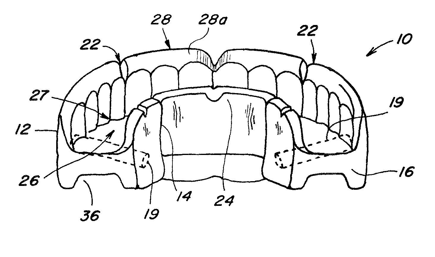
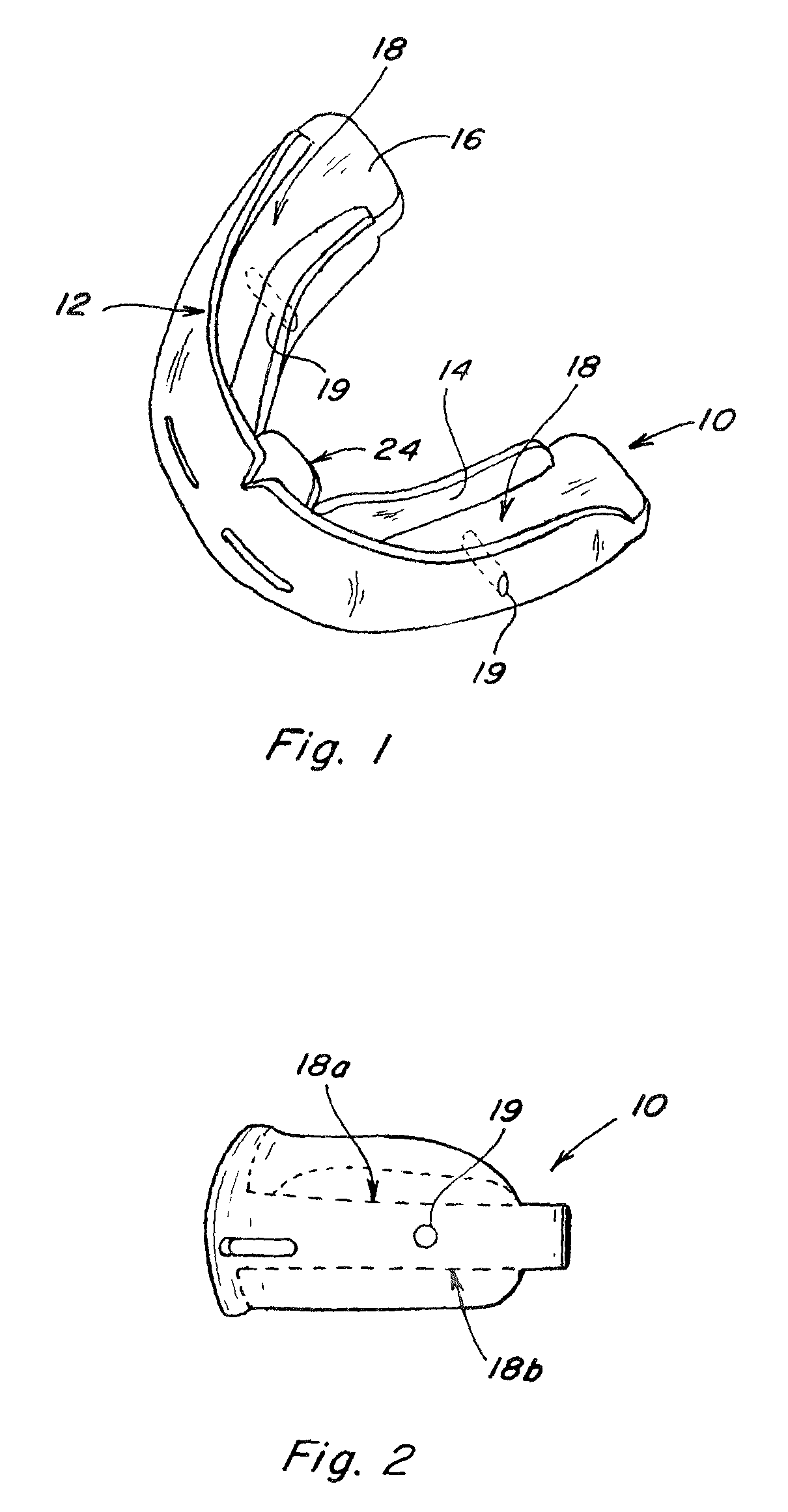
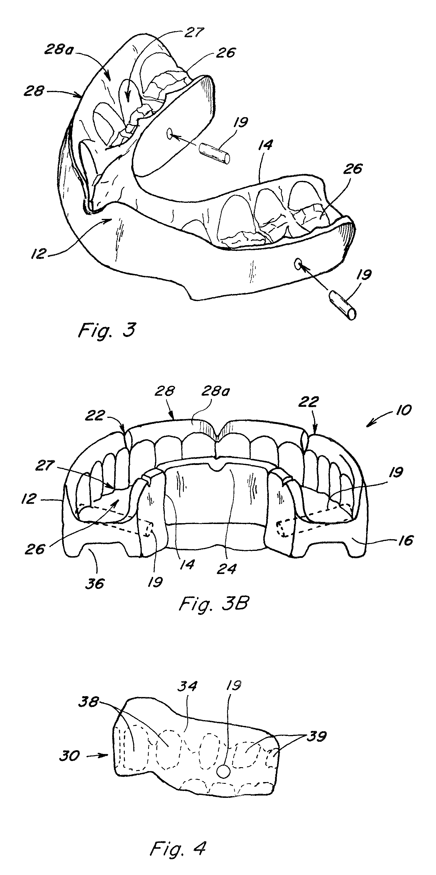
[0030]With reference to the drawings, and in particular to FIG. 1, the performance enhancing boil and bite mouth guard construction 10 of the present invention is adapted for insertion into a user's mouth and for protective engagement with the user's teeth, prior to being heated for personalization and teeth impressions. The mouth guard 10 is generally U-shaped and is comprised of labial wall 12, lingual wall 14 which are upstanding from base 16, and channel 18 is formed by this arrangement. A pre-formed non-softenable pin 19 is embedded on each of the right posterior side and left posterior side of the base 16. The top surface portion 18a of channel 18 and bottom surface portion 18b are located immediately above and below respective areas relative to pin 19 and are referred to as the top bite portion 18a and bottom bite portion 18b, which appear on the right and the left side of mouth guard 10.

[0031]Mouth guard 10 having been made of predominantly softenable thermoplastic material ...


PUM


Abstract

An improved performance enhancing mouth guards having transverse pins embedded in the right and left posterior occlusal base portion of the mouth guard, is disclosed.

Description

[0001]This application claims the benefit of U.S. Provisional Application No. 61 / 094,221, filed Sep. 4, 2008.TECHNICAL FIELD[0002]This invention relates generally to performance enhancing and force absorbing mouth guards, and more particularly to a novel construction for self-fitting boil and bite mouth guards.BACKGROUND ART[0003]A number of mouth guards currently exist, in the art, for protecting the teeth and for reducing the chance of shock, concussions, and other injuries. These prior art mouth guards are also known to place the lower jaw in the so-called power position, moving the condyle within the temporomandibular joint (TMJ), forwardly away from the nerves and arteries found within the fossa or socket of the joint. In doing so, the mouth guards raise body muscular strength, provide greater endurance, and generally improve physical performance. However, such mouth guards tend to be complex in construction and very expensive.[0004]There are two (2) categories of these prior a...

Claims


Application Information

Patent Timeline
Patent Type & Authority Patents(United States)
IPC IPC(8): A61C5/14
CPCA63B71/085
Inventor QUIGLESS, KIRK, C.
Owner QUIGLESS KIRK C
Learn More