
Magnetic trigger mechanism

a trigger mechanism and magnetic technology, applied in the field of magnetic triggers, can solve the problems of large metallic friction, inability of conventional structures to compensate for this tilt, and difficulty in guiding the armature and/or orienting the armature on the socket, etc., and achieves short trigger time, high energy yield, and small trigger energy.

Active Publication Date: 2014-03-11
JOHNSON ELECTRIC DRESDEN
View PDF30 Cites 11 Cited by
  • Summary
  • Abstract
  • Description
  • Claims
  • Application Information

AI Technical Summary

Benefits of technology

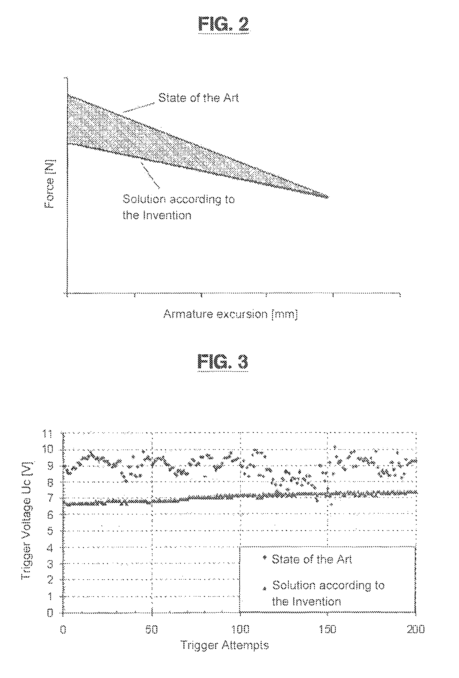
The technical effect of the patent is to create a magnetic trigger that has a low trigger energy but produces a high energy yield and short trigger time.

Problems solved by technology

Conventional structure are unable to compensate for this tilt.
Tighter guides would also cause jamming.
However, the solutions advantageous for the spring constant make it difficult to guide the armature and / or orient the armature on the socket.
However, large metallic friction is observed when the spring is guided in the armature.
Both effects are undesirable.

Method used


Image

  • Magnetic trigger mechanism
  • Magnetic trigger mechanism
  • Magnetic trigger mechanism

Examples


Embodiment Construction

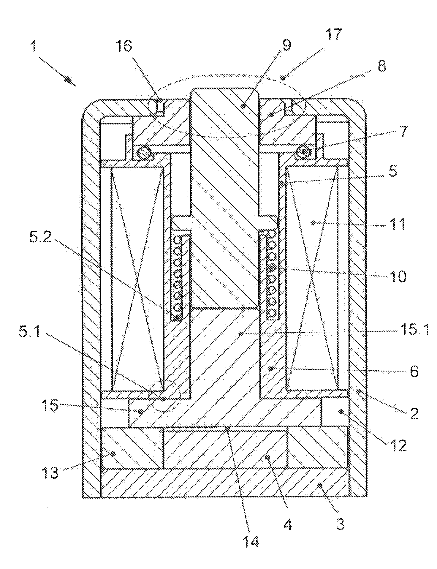
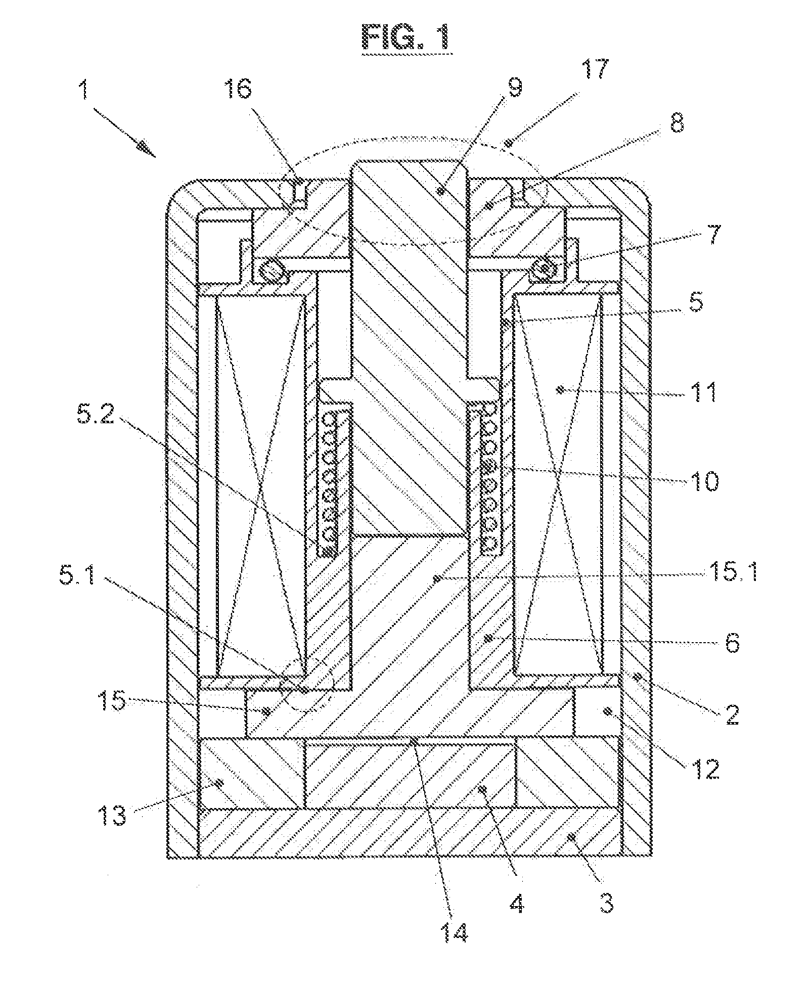
[0038]FIG. 1 shows a cross-sectional view of the magnetic trigger 1 according to the invention. The yoke 2 of the magnetic trigger 1 is made of a housing or frame with an armature opening 17 disposed on a first end face and a base plate for closing the housing disposed on a second opposite end face. An excitation coil 11 as well as a coil body 5 receiving the excitation coil 11 are disposed inside the yoke 2. The coil body 5 has a guide constructed as a guide sleeve which is provided with a coaxial groove 5.2. A spring element 10 formed as a compression spring is disposed in this groove 5.2. The armature 9 is guided in one half of the guide sleeve. The journal 15.1 of the socket 15 which is made of a highly permeable material is pressed into the other half of the guide sleeve. The second end of the armature 9 facing the armature opening 17 is additionally guided through a centering ring 8 disposed in the armature opening 17. The tolerance chain thus remains short and the armature 9 ...


PUM

PropertyMeasurementUnit
forceaaaaaaaaaa
magnetic holding forceaaaaaaaaaa
areaaaaaaaaaaa

Abstract

A magnetic trigger mechanism with a yoke with armature opening. The armature is coaxially surrounded by a coil having an excitation coil, which is acted on by a force of a preloaded spring and which remains in a first end position due to magnetic holding force of a permanent magnet when there is no current flowing through the excitation coil. The permanent magnet is arranged at a first end of the armature and the second end position of the armature being achieved by a brief flow of current through the excitation coil together with the accompanying lowering of the magnetic holding force and the spring force. The first end of the armature is guided in the coil body, and the second end position, which faces the armature opening, is guided by a centering ring, the highly permeable centering ring rests against the yoke at the armature opening and can move.

Description

[0001]This is an application filed under 35 USC §371 of PCT / DE2010 / 000694, claiming priority to DE 10 2009 030 479.7 filed on Jun. 24, 2009.BACKGROUND OF THE INVENTION[0002]The invention relates to a magnetic trigger which has at least a yoke having an armature opening, an armature disposed inside yoke, wherein the armature is coaxially surrounded by at least one section of the coil body having at least one excitation coil and is biased by the force of a preloaded spring element, wherein when current is not flowing through the excitation coil, the armature remains in a first end position due to the magnetic holding force of a permanent magnet, wherein the permanent magnet together with a socket extending between the armature and the permanent magnet are arranged in the area of the first end of the armature, and the second end position of the armature is attained by briefly flowing a current through the excitation coil together accompanied by a reduction of the magnetic holding force...

Claims


Application Information

Patent Timeline
Patent Type & Authority Patents(United States)
IPC IPC(8): H01F7/00
CPCH01F2007/1669H01H71/322H01F7/1615H01F7/13
Inventor KULKE, MATTHIASROECHKE, THOMAS
Owner JOHNSON ELECTRIC DRESDEN
Learn More