Systems and methods for refractive correction in visual field testing

a technology of visual field and refractive correction, applied in the field of visual field testing, can solve the problems of reducing the reliability of visual field test, providing cumbersome and time-consuming methods for reducing refractive blur, and general depression of visual field

Active Publication Date: 2014-03-11
CARL ZEISS MEDITEC INC
View PDF40 Cites 13 Cited by
  • Summary
  • Abstract
  • Description
  • Claims
  • Application Information

AI Technical Summary

Problems solved by technology

Although a set of trial lenses are available in most clinical settings, they provide a cumbersome and time consuming method of reducing refractive blur during a visual field test.
There are also a number of negatives associated with trial lenses leading to reduced reliability of the visual field test.
Mistakes in selecting the correct trial lens can cause a general depression of the visual field.
Furthermore, the patient's comfort is often reduced by the use of trial lenses and overall workflow in the office setting is significantly slowed down.

Method used


Image

  • Systems and methods for refractive correction in visual field testing
  • Systems and methods for refractive correction in visual field testing
  • Systems and methods for refractive correction in visual field testing

Examples


second embodiment

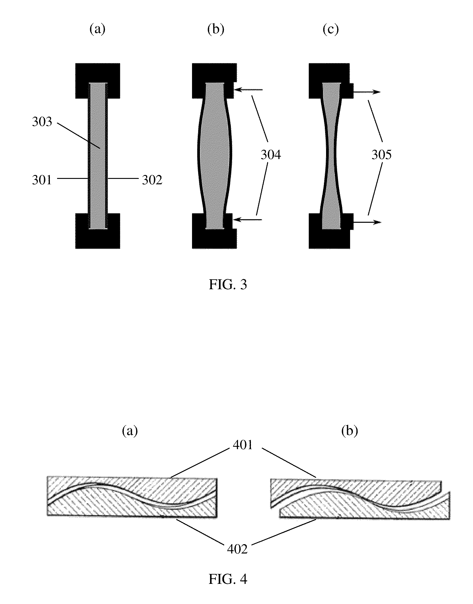
[0018]In the lens system illustrated in FIG. 3, a liquid lens is utilized to provide a variable refractive correction. A liquid lens typically consists of one or two transparent and flexible membranes 301 and 302, encapsulating a volume of liquid 303 with a specific refractive index. A variety of liquid lenses have been described in the literature. Continuously adjustable refractive positive or negative powers of up to 25-50 diopters have been demonstrated [see for example http: / / www.holochip.com and Ren et. al “Variable-focus liquid lens by changing aperture” Applied Physics Letters 86:21107 2005 hereby incorporated by reference]. An actuator changes the distribution of the volume of the liquid, to adjust the refractive power of the lens as shown pictorially in FIGS. 3(b) and 3(c) creating convex and concave lenses respectively. In this case pressure is applied or released to the periphery of the lens as indicated by arrows 304 and 305. The volume change can be accomplished either ...

third embodiment

[0019]In a variable lens system two or more transmissive plates of different shapes are translated perpendicular to the optical axis or rotated around the axis to produce a change in refractive power. One example of such a system is an Alvarez lens system. This lens system, invented by Luis W. Alvarez in the 1960s (see U.S. Pat. No. 3,305,294 hereby incorporated by reference) and illustrated in FIG. 4, consists of two transmissive plates 401 and 402, where each plate has a flat surface and a surface shaped in a specific two-dimensional polynomial shape. Parallel translation of the two plates relative to each other produces a change in refractive power, e.g., spherical and / or cylindrical as illustrated in FIGS. 4(a) and (b). Various embodiments of lens systems incorporating the general principle of shifting or rotating transmissive plates relative to each other to create variations in spherical and cylindrical power would be known by those skilled in the art. Instead of or in additio...


PUM


Abstract

Systems and methods for providing variable refractive correction in a visual field testing device are presented. One embodiment of the variable refractive correction involves two or more aligned transmissive plates arranged to produce changes in refractive power by translation or rotation of the plates relative to each other. Several alternative designs for providing variable refractive correction are described. The refractive correction can be set manually or automatically based on knowledge of the refractive error of a specific patient and spherical and cylindrical refractive correction are possible. Additional lens systems can be used to extend the range of refractive correction to accommodate a larger patient population.

Description

CROSS-REFERENCE TO RELATED APPLICATIONS[0001]This application claims priority to U.S. Provisional Application Ser. No. 61 / 453,860, filed Mar. 17, 2011, the entire disclosure of which is incorporated by reference.TECHNICAL FIELD[0002]Various embodiments of the present invention relate generally to the field of visual field testing. In particular, the invention is directed towards an improved means of correcting the refractive error in a perimeter or other visual field testing device to increase the reliability of the visual field test, improve the ease of use of the instrument, and improve patient comfortBACKGROUND OF THE INVENTION[0003]To achieve a reliable result on a visual field test it is important to correct the patient's refractive error, since refractive blur will reduce the visual sensitivity to perimetric stimuli. Today, it is standard practice to reduce the refractive error to within 1 diopter, which would produce less than one decibel of depression of the hill of vision w...

Claims


Application Information

Patent Timeline
Patent Type & Authority Patents(United States)
IPC IPC(8): A61B3/02
CPCA61B3/024A61B3/0285
Inventor JOHANSSON, GORAN ANDERSEVERETT, MATTHEW J.BAKER, CHRISTOPHER J. R. V.
Owner CARL ZEISS MEDITEC INC
Why Eureka
Try Eureka