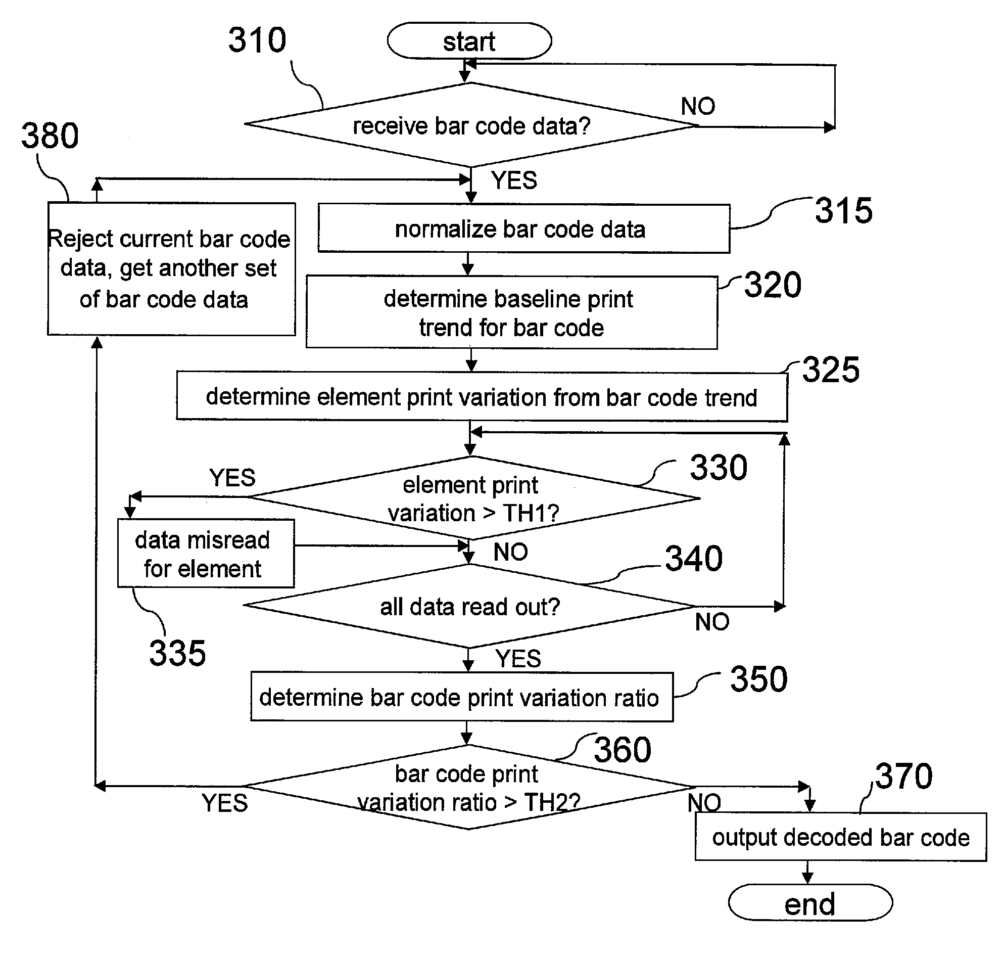
Bar code reader terminal and methods for operating the same having misread detection apparatus
a bar code reader and detection apparatus technology, applied in the field of data terminals, can solve the problems of inability to sharply represent bar codes, inability to decode decodable indicia such as bar codes, and inability to read bar codes accurately, so as to increase the read data rate
- Summary
- Abstract
- Description
- Claims
- Application Information
AI Technical Summary
Benefits of technology
Problems solved by technology
Method used
Image

Examples
Embodiment Construction
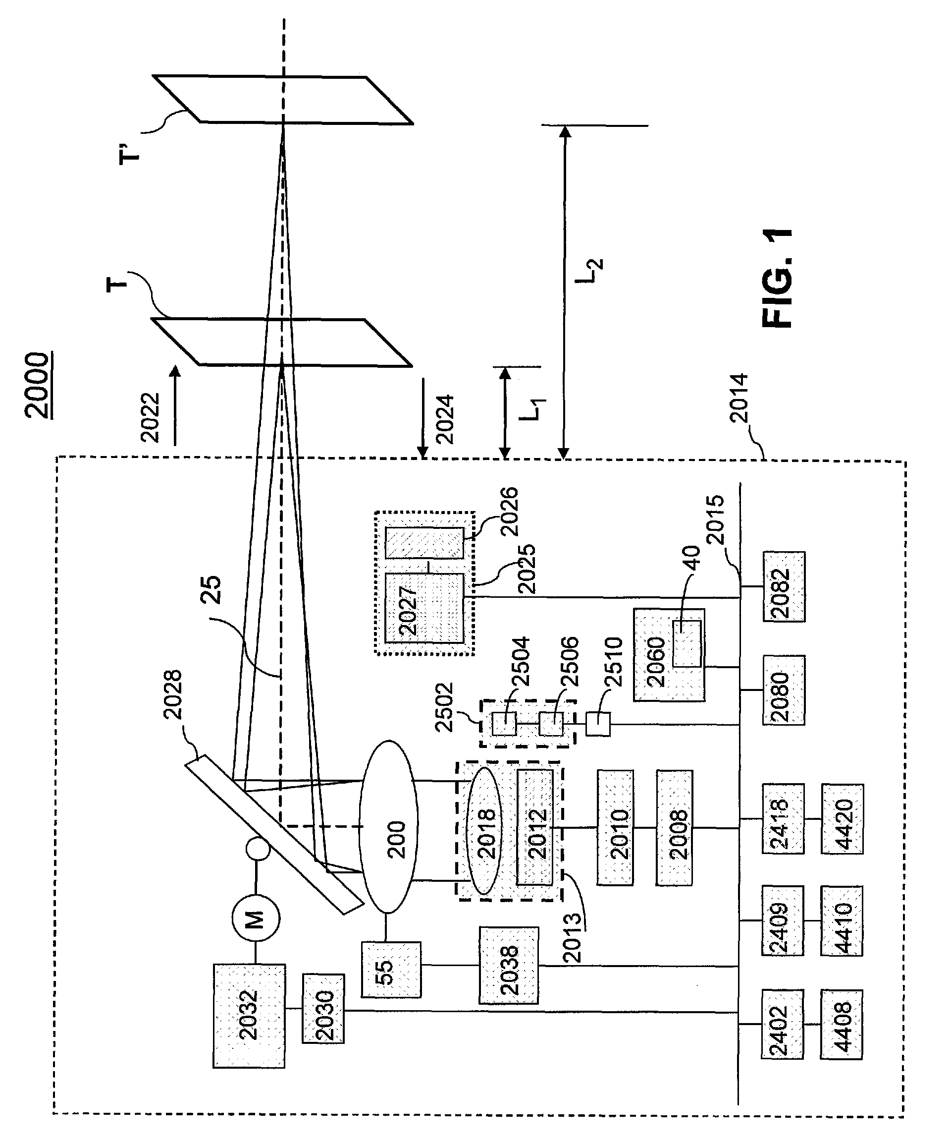
[0014]Referring to FIG. 1, an indicia reading terminal 2000 includes a laser source 2012. The laser source 2012 can emit a laser beam along an optical path, e.g., axis 25. Laser source 2012 can be coupled to laser source control circuit 2010. Light from laser source 2012 can be shaped by optical assembly 2018 (e.g., collimating optics) and optional lens assembly 200. The combination of laser source 2012 and optics 2018 can be regarded as a laser diode assembly 2013. The laser beam travels in an emitting direction 2022 along axis 25 and illuminates a target T, which in one embodiment includes a decodable indicia such as a bar code. A scanning mirror reflector 2028 disposed within the optical path defined by axis 25 oscillates to direct the laser beam across a surface to be scanned. Reflector 2028 can be driven by scan motor, M, which is coupled to control circuit 2032.
[0015]The laser beam reflects off the target T and scattered light travels along axis 25 in a receiving direction 202...
PUM
 Abstract
Description
Claims
Application Information
 - R&D
- Intellectual Property
- Life Sciences
- Materials
- Tech Scout
- Unparalleled Data Quality
- Higher Quality Content
- 60% Fewer Hallucinations
Browse by: Latest US Patents, China's latest patents, Technical Efficacy Thesaurus, Application Domain, Technology Topic, Popular Technical Reports.
© 2025 PatSnap. All rights reserved.Legal|Privacy policy|Modern Slavery Act Transparency Statement|Sitemap|About US| Contact US: help@patsnap.com