Non-contact power supply system
a power supply system and non-contact technology, applied in the direction of pulse generators, safety/protection circuits, pulse techniques, etc., to achieve the effects of enhancing signal transmission reliability, suppressing power waste, and reducing power consumption
- Summary
- Abstract
- Description
- Claims
- Application Information
AI Technical Summary
Benefits of technology
Problems solved by technology
Method used
Image
Examples
first embodiment
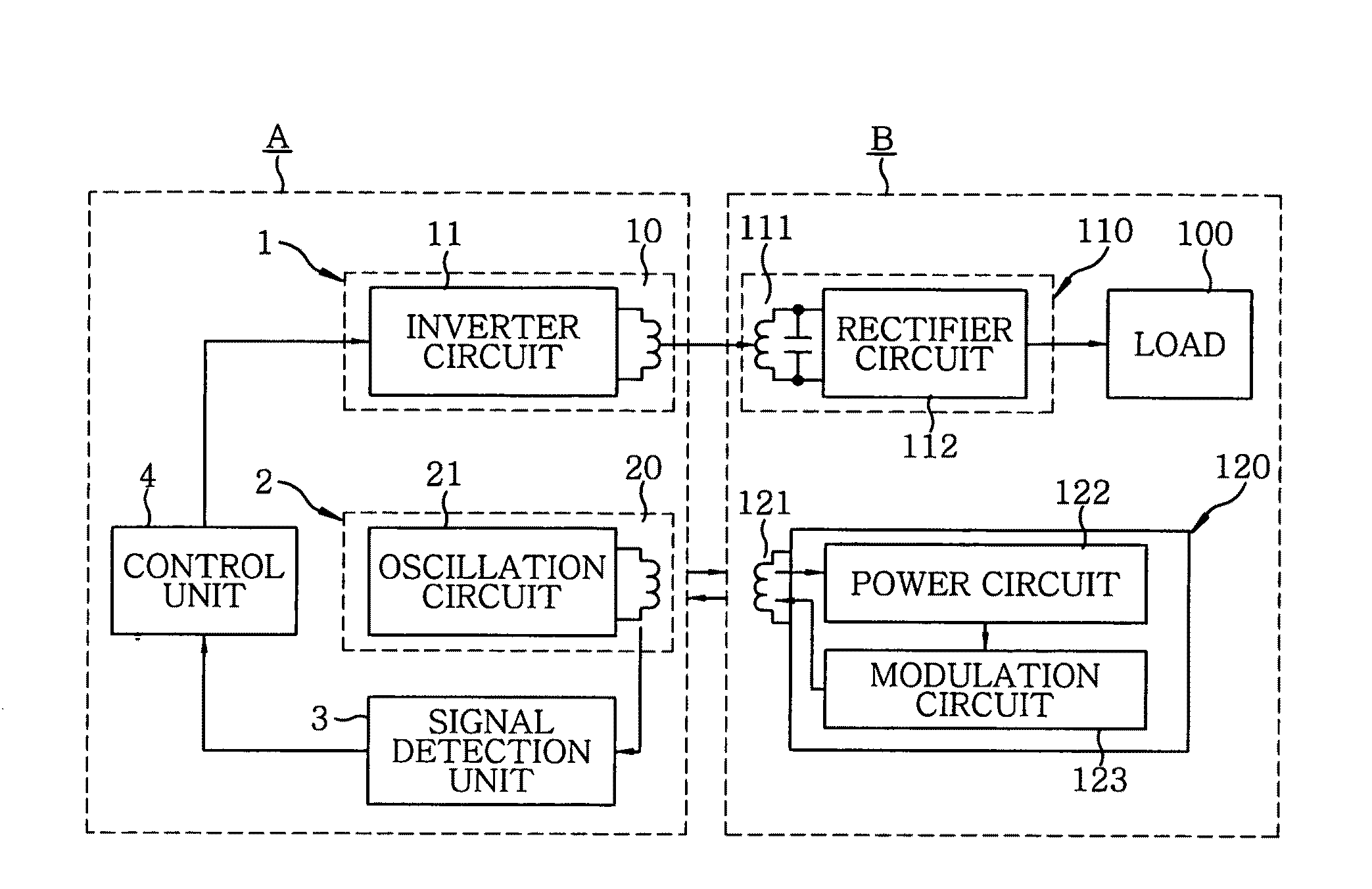
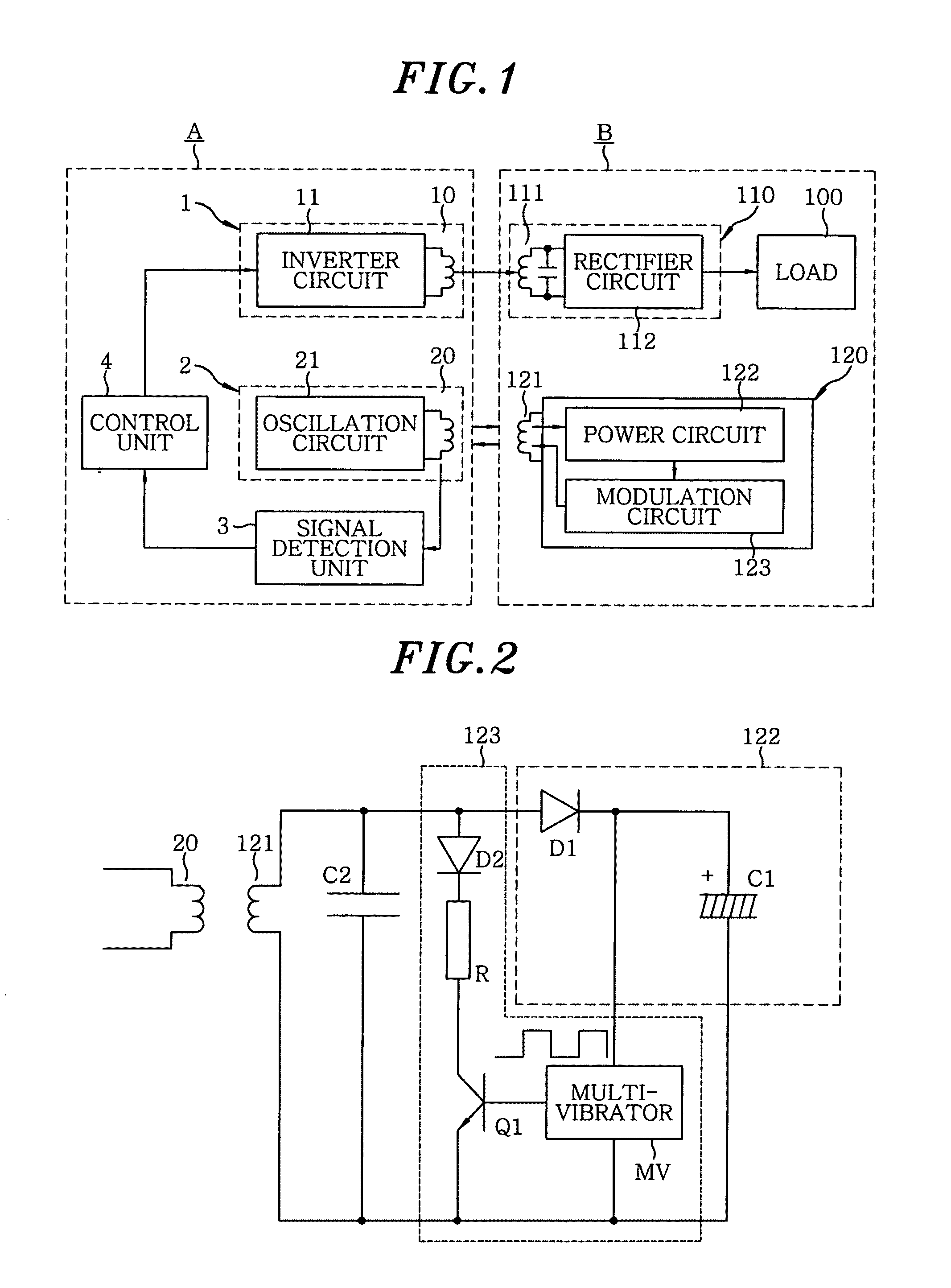
[0065]A non-contact power supply system in accordance with a first embodiment of the present invention includes, as shown in FIG. 1, a power supply device A which transmits high frequency power and a load device B which receives the high frequency power transmitted from the power supply device A in a non-contact mode by electromagnetic induction to supply the power to a load.
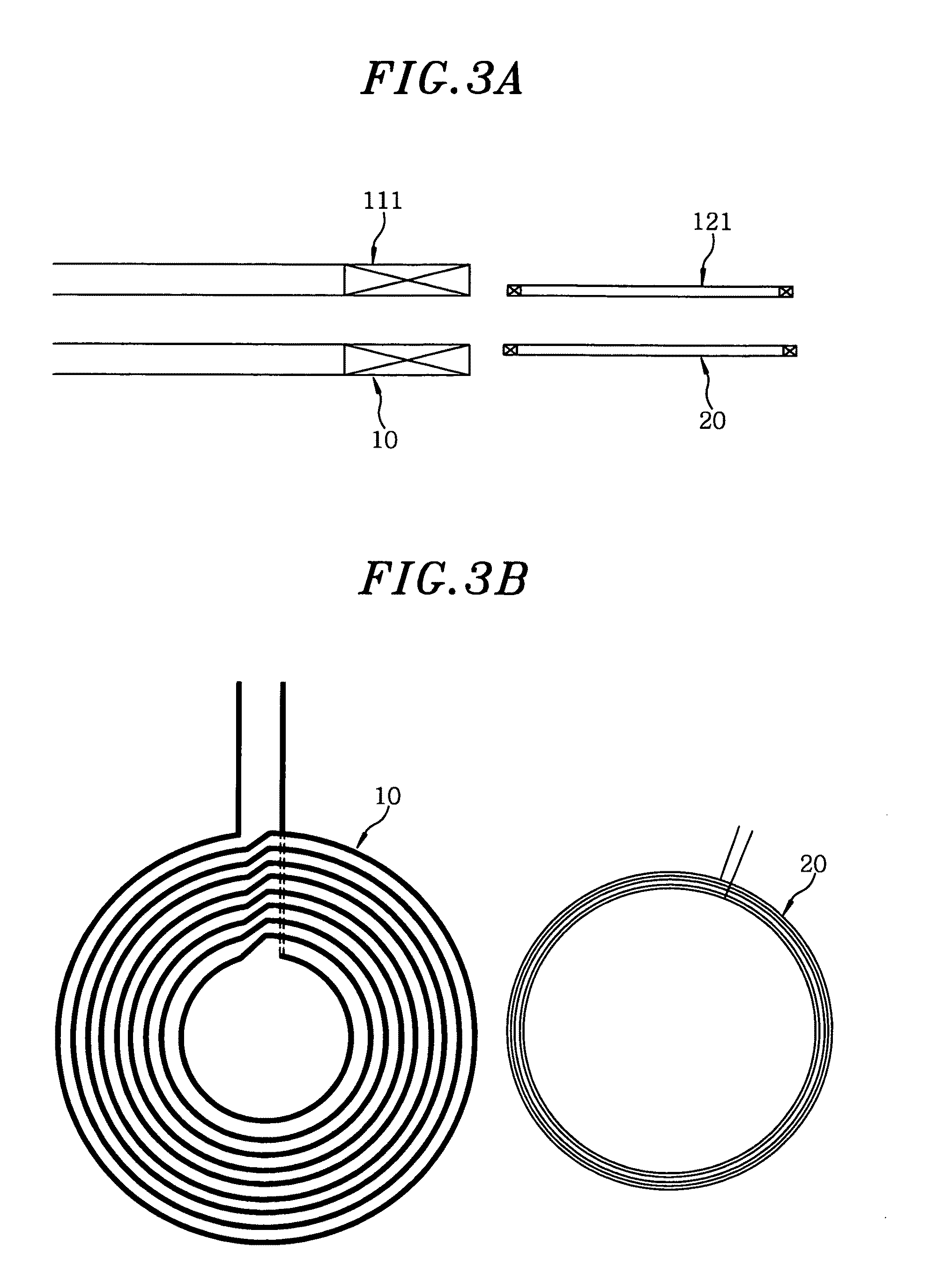
[0066]The power supply device A includes a power transmission unit 1 having a primary power coil 10 for power transmission and an inverter circuit 11 for supplying high frequency current to the primary power coil 10, and an inquiry unit 2 having a primary signal coil 20 for transmitting / receiving a signal to / from the load device B and an oscillation circuit 21, the primary signal coil 20 being connected between output terminals of the oscillation circuit 21. The power supply device A further includes a signal detection unit 3 for detecting the signal received by the primary signal coil 20, and a control unit 4 f...
second embodiment
[0105]A non-contact power supply system in accordance with a second embodiment of the present invention, as shown in FIG. 12, has a feature that the load device B further includes a load device control unit 130 for transmitting a control command from the response unit 120 to the control unit 4 of the power supply device A to instruct stop of power transmission of the power transmission unit 1 or reduction of the transmission power level. Since other configurations are same as those of the first embodiment, the same components as those of the first embodiment will be assigned with the same reference numerals and explanation thereof will be omitted.
[0106]For example, if the load 100 is a secondary battery and the power is continuously supplied from the power supply device A even after the secondary battery is fully charged, the power is wasted. In such a case, it may be considered to provide a switch element (semiconductor switch element or relay) in a power supply path between the po...
third embodiment
[0108]A non-contact power supply system in accordance with a third embodiment of the present invention, as shown in FIG. 13, has a feature that a second power circuit 113 for producing operation power of the response unit 120 from the high frequency power induced in the secondary power coil 111 is provided in the power reception unit 110 of the load device B. Further, since other configurations are same as those of the first embodiment, the same components as those of the first embodiment will be assigned with the same reference numerals and explanation thereof will be omitted.
[0109]The second power circuit 113 supplies DC power to the modulation circuit 123 of the response unit 120, the DC power being produced by rectifying and smoothing the high frequency power induced in the secondary power coil 111 when the power is supplied from the power transmission unit 1 to the power reception unit 110.
[0110]That is, the amount of the power transmitted from the inquiry unit 2 of the power s...
PUM
| Property | Measurement | Unit |
|---|---|---|
| frequency | aaaaa | aaaaa |
| frequency | aaaaa | aaaaa |
| frequency | aaaaa | aaaaa |
Abstract
Description
Claims
Application Information
 - R&D
- Intellectual Property
- Life Sciences
- Materials
- Tech Scout
- Unparalleled Data Quality
- Higher Quality Content
- 60% Fewer Hallucinations
Browse by: Latest US Patents, China's latest patents, Technical Efficacy Thesaurus, Application Domain, Technology Topic, Popular Technical Reports.
© 2025 PatSnap. All rights reserved.Legal|Privacy policy|Modern Slavery Act Transparency Statement|Sitemap|About US| Contact US: help@patsnap.com


