
Methods, assemblies, and devices for positioning a catheter tip using an ultrasonic imaging system

a catheter tip and ultrasonic imaging technology, applied in the direction of catheters, applications, guide wires, etc., can solve the problems of catheter malfunction, catheter delay, additional cost,

Active Publication Date: 2014-03-04
ANGIODYNAMICS INC
View PDF71 Cites 41 Cited by
  • Summary
  • Abstract
  • Description
  • Claims
  • Application Information

AI Technical Summary

Benefits of technology

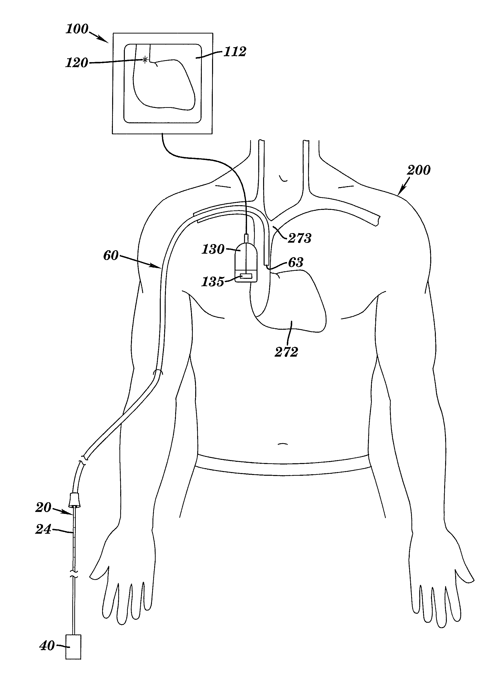
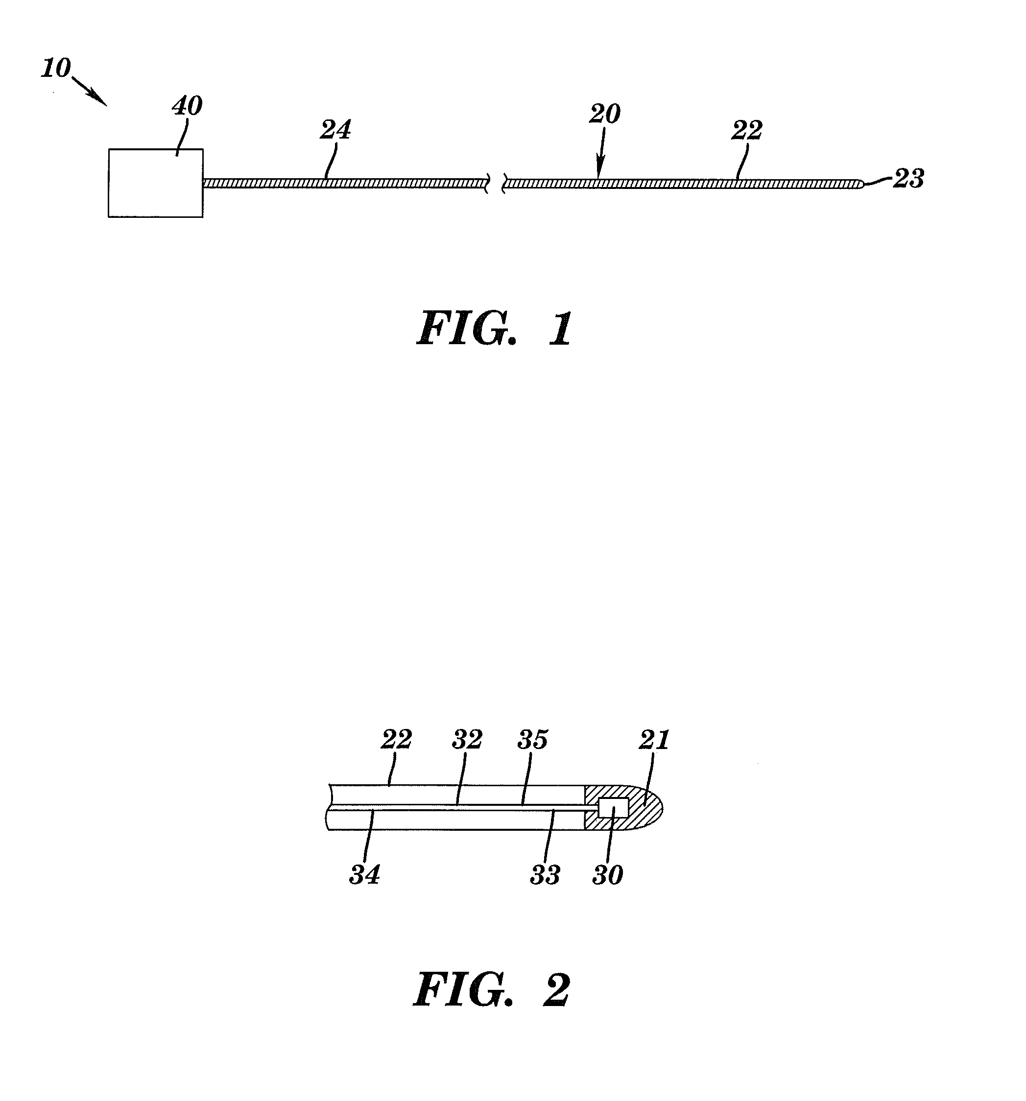
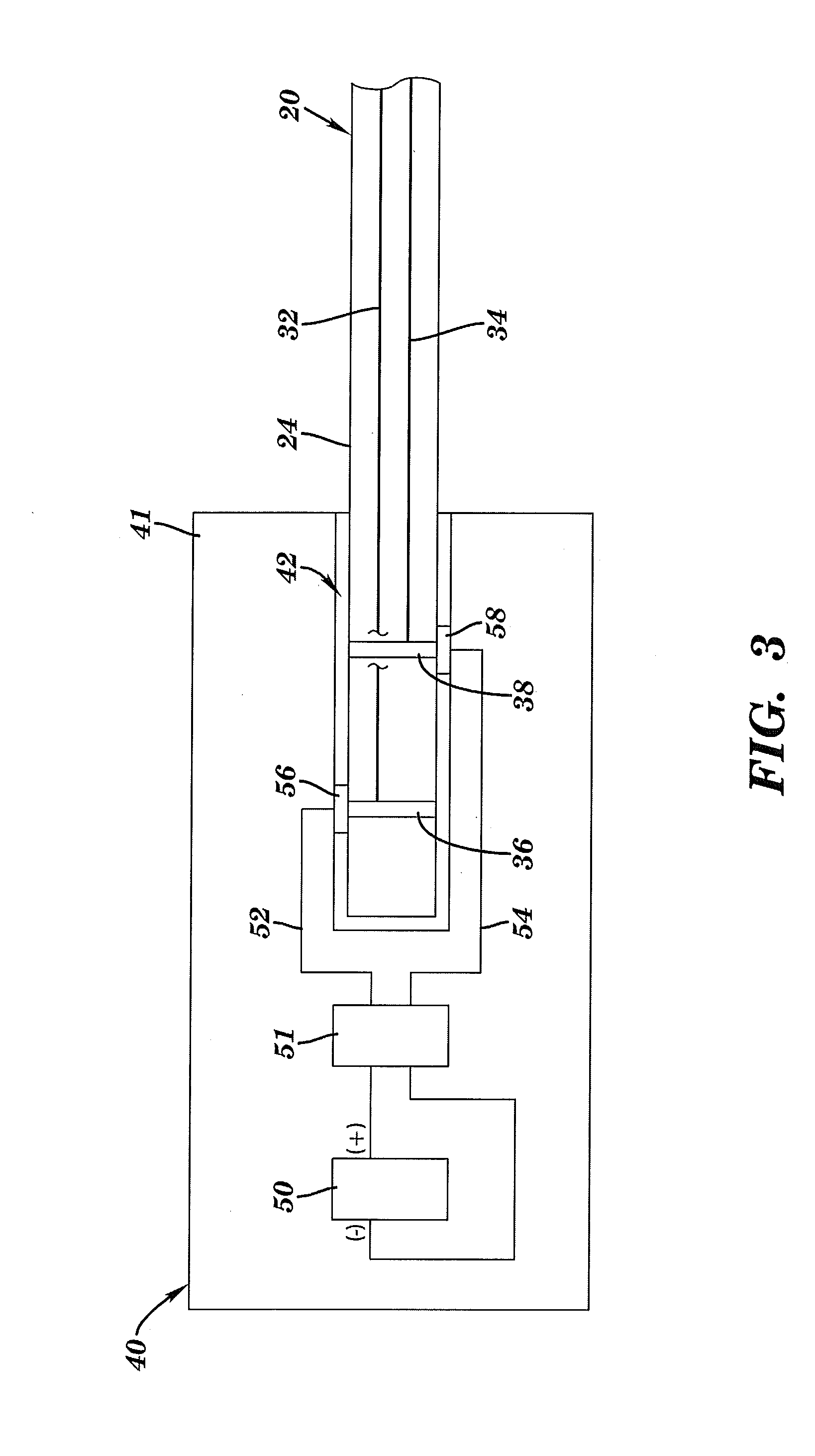
The present invention provides a method for positioning a catheter tip within a human body using an elongated member with a proximal end and a distal end. The distal end of the elongated member has an ultrasonic beacon attached to it, which is powered by a power supply also attached to the proximal end. The elongated member is inserted into the anatomical structure of the human body, and an ultrasonic transmitter / receiver is positioned adjacent to the outer surface of the human body. The ultrasonic beacon is powered and an ultrasound image of the internal structure of the human body is obtained. The catheter tip is then positioned relative to the elongated member and the elongated member is removed from the catheter. This invention allows for easier and more accurate positioning of the catheter tip within the human body.

Problems solved by technology

However, if the catheter tip is improperly positioned during insertion, or if the catheter tip migrates out of position after insertion, various risks arise, including a fluid infusion that causes pain or injury to the patient, complications due to increased thrombosis rates, delays in therapy, catheter malfunction and additional costs.
However, since PICCs are commonly inserted into a vein in the arm and advanced through the venous system to reach the superior vena cava, the PICC line tip may be inadvertently positioned in a non-target area, such as the internal jugular or subclavian vein.
Further, even if a PICC is property inserted, the catheter tip could later shift out of position if for example the patient coughs violently, moves a lot, or experiences severe vomiting.

Method used


Image

  • Methods, assemblies, and devices for positioning a catheter tip using an ultrasonic imaging system
  • Methods, assemblies, and devices for positioning a catheter tip using an ultrasonic imaging system
  • Methods, assemblies, and devices for positioning a catheter tip using an ultrasonic imaging system

Examples


Embodiment Construction

[0028]The present invention can be understood more readily by reference to the following detailed description, the examples included therein, and to the drawing figures. The drawings, which are not necessarily to scale, depict selected preferred embodiments and are not intended to limit the scope of the invention. The detailed description illustrates by way of example, not by way of limitation, the principles of the invention. The skilled artisan will readily appreciate that the devices and methods described herein are merely examples and that variations can be made without departing from the spirit and scope of the invention. It is also to be understood that the terminology used herein is for the purpose of describing particular embodiments only and is not intended to be limiting.

[0029]As explained in greater detail below, the present invention in one aspect is directed to methods and apparatus for positioning and / or confirming a desired location of a catheter tip of a catheter in ...


PUM


Abstract

A catheter assembly includes an elongated member having an ultrasonic beacon disposed adjacent to a distal end portion of the elongated member, a power supply releasably attachable adjacent to the proximal end of the elongated member, and a catheter. The distal end portion of the elongated member with the ultrasonic transmitter is inserted into an anatomical structure of the human body, and the ultrasonic transmitter is powered by the power supply. Using conventional medical ultrasonography equipment, a technician is able to observe and / or track on a display an image of the internal structure of the human body and an image such as an illuminated bright spot representing the energized ultrasonic beacon. After locating the elongated member, the power supply is removed, and the catheter is slid onto the elongated member to locate the catheter tip. Thereafter, the elongated member is removed.

Description

FIELD OF THE INVENTION[0001]The present invention relates generally to positioning a catheter tip such as within a human body. More specifically, the invention relates to methods, assemblies, and devices for positioning a catheter tip using an ultrasonic imaging system.BACKGROUND OF THE INVENTION[0002]Medical professionals commonly use catheters for gaining prolonged access to an area within the body. Once the catheter tip is positioned at the target location, treatments such as antibiotics, chemotherapy, pain medicine, and nutrition can be administered. However, if the catheter tip is improperly positioned during insertion, or if the catheter tip migrates out of position after insertion, various risks arise, including a fluid infusion that causes pain or injury to the patient, complications due to increased thrombosis rates, delays in therapy, catheter malfunction and additional costs.[0003]The general standard for proper catheter insertion depends on the type of catheter and the t...

Claims


Application Information

Patent Timeline
Patent Type & Authority Patents(United States)
IPC IPC(8): A61B8/14
CPCA61B2019/5263A61B8/0841A61B2019/5429A61B8/12A61M25/0102A61M25/0108A61M25/09A61M2025/0008A61M2210/12A61B2034/2063A61B2090/3929
Inventor HAMILTON, JR., WILLIAM, C.
Owner ANGIODYNAMICS INC
Learn More