
Variable-length, adjustable spacer

a spacer, variable-length technology, applied in the direction of sheet joining, fastening means, washers, etc., can solve the problems of relative imprecise means for mounting, complicating the mounting of gas outlet boxes to the wall, and the use of spacers may be relatively complicated

Active Publication Date: 2014-02-18
BUDDE HORST
View PDF21 Cites 219 Cited by
  • Summary
  • Abstract
  • Description
  • Claims
  • Application Information

AI Technical Summary

Benefits of technology

The patent introduces a new type of adjustable spacer that solves previous problems. The goal is to improve this type of spacer.

Problems solved by technology

Such a procedure may be a time consuming and may result in a relatively imprecise means for mounting.
Also, variations in the type of wall finish, such as siding, stucco finishes and other wall finishes, which may or not form a flat vertical plane, further complicate the mounting of gas outlet boxes to the wall.
The above set out adjustable spacers may be relatively complicated to use, may require a relatively large number of parts and / or may be relatively costly to manufacture.

Method used


Image

  • Variable-length, adjustable spacer
  • Variable-length, adjustable spacer
  • Variable-length, adjustable spacer

Examples


Embodiment Construction

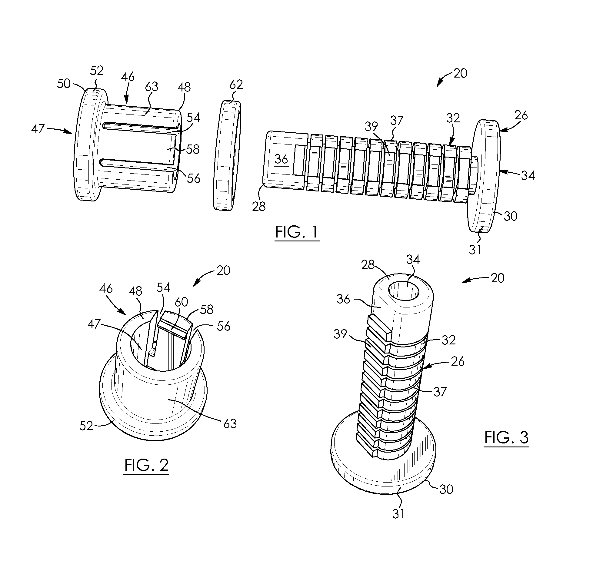
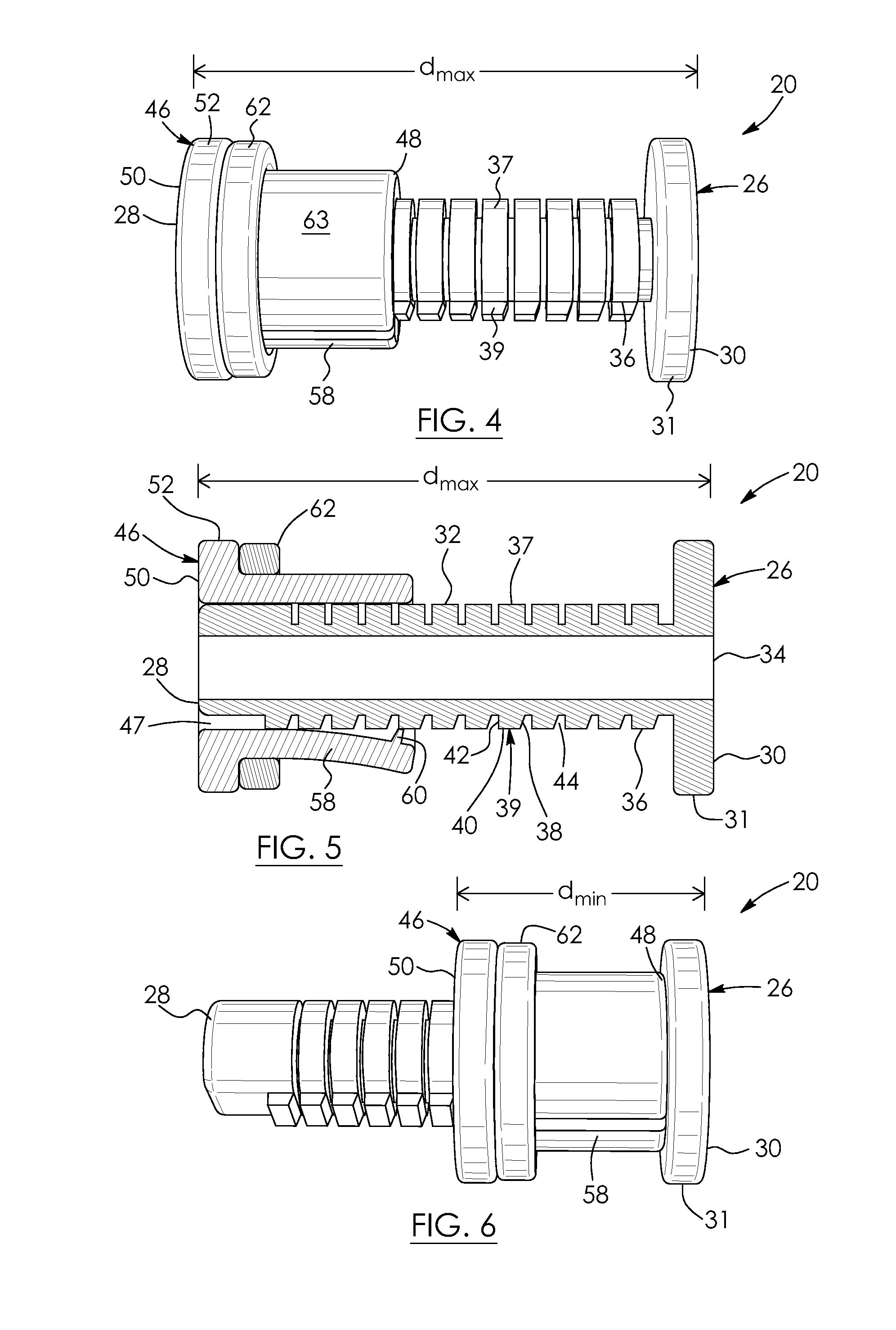
[0024]Referring to the drawings and first to FIG. 1, there is shown a variable-length, adjustable spacer, in this example an adjustable standoff 20 for mounting a receptacle, in this example a gas outlet box 22 seen in FIG. 10, to a surface, in this example wall 24. The standoff may be used for mounting other receptacles or objects to a wall instead of the outlet box. Also, the surface need not be a wall 24: for example, it may be, in the alternative, a ceiling or a floor. The standoff 20 is made of a polymer, in this example, though this is not strictly required. Referring back to FIG. 1, the standoff includes an elongate member 26 that is generally cylindrical in shape. The elongate member has a first end 28 and a flanged second end 30 spaced-apart from the first end. The elongate member 26 has an enlarged portion, in this example a flange 31 at its second end. Second end 30 is thus enlarged relative to end 28 and may be referred to as an outer end. First end 28 may be referred to...


PUM


Abstract

The present invention relates to an adjustable spacer. The spacer includes an elongate member. The spacer includes a sleeve extendable around the elongate member. The elongate member is moveable relative to the sleeve. The sleeve has a locking member. The spacer includes an engaging member configured to selectively engage the locking member for inhibiting movement of the sleeve relative to the elongate member when a desired spacing of the elongate member relative to the sleeve is determined.

Description

FIELD OF THE INVENTION[0001]There is provided an adjustable spacer. In particular, there is provided a variable-length, adjustable spacer for mounting a receptacle to a wall, ceiling or floor.DESCRIPTION OF THE RELATED ART[0002]In the gas appliance industry, the end of a gas pipe will typically extend outwards from the wall of a house. This pipe connects to a gas outlet box. In order to connect the outlet box to the wall of the house, typically a spacer or standoff is used.[0003]Fixed-length standoffs are known per se and are sold in a series of specific spacer sizes. However, there may be variations in the extent to which the pipe extends from the wall of the house. This may require shimming of the fixed-length standoffs to properly mount the outlet box to the wall. Such a procedure may be a time consuming and may result in a relatively imprecise means for mounting.[0004]Also, variations in the type of wall finish, such as siding, stucco finishes and other wall finishes, which may ...

Claims


Application Information

Patent Timeline
IPC IPC(8): F16B43/00
CPCF16B43/00F16B5/0233
Inventor BUDDE, HORST
Owner BUDDE HORST
Learn More