
Water management and cooling during electrolysis

a technology of electrolysis and water management, applied in the field of water management and cooling during electrolysis, can solve the problems of inefficiency of electrolyser, high parasitic energy demand inherent in pumping and circulation, and a small fraction of the total cost of the electrolyser system, so as to reduce catalyst degradation, reduce the potential for cheaper catalysts, and maintain the effect of hydration

Active Publication Date: 2014-02-11
ITM POWER (RES) LTD
View PDF6 Cites 1 Cited by
  • Summary
  • Abstract
  • Description
  • Claims
  • Application Information

AI Technical Summary

Benefits of technology

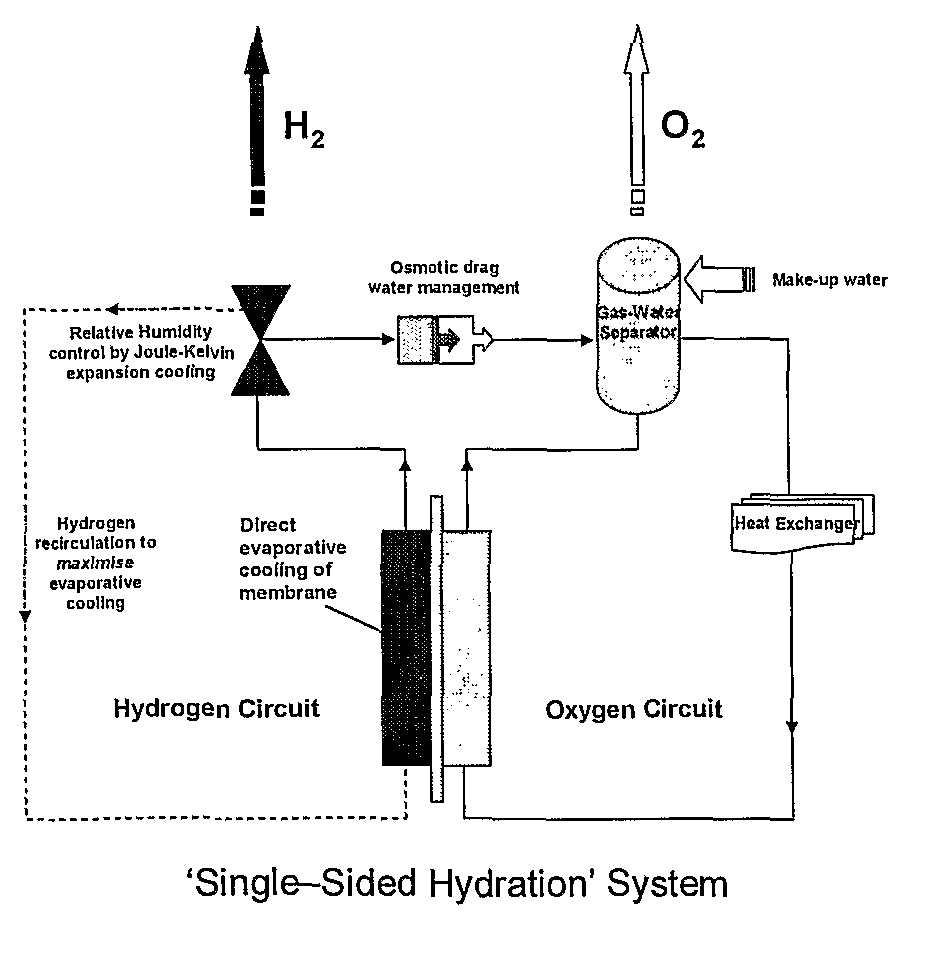
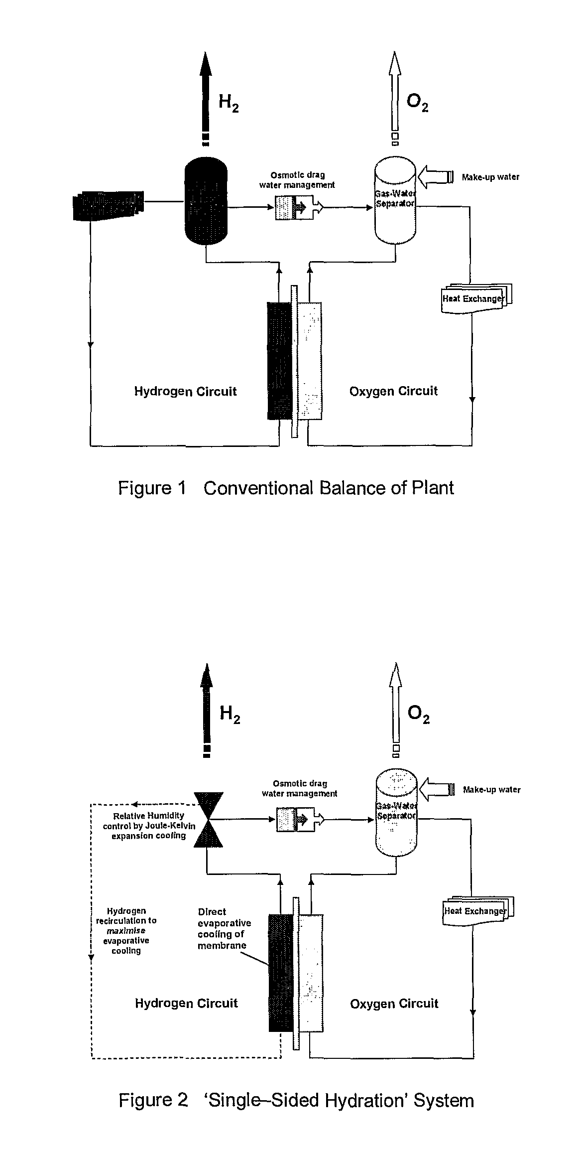
[0017]It has surprisingly been found that the cooling in the known one-sided CE electrolysers can be improved by re-circulating hydrogen in the dry electrode compartment (cathode). When re-circulated, hydrogen acts as a coolant, which improves evaporative cooling from the hydrogen side of the membrane. The advantages of this are that the need for expensive heat exchanger cooling systems is minimised.
[0026]It has also surprisingly been found that, by using an electrolyser having a hydrophilic anionic exchange (AE) membrane, hydration can be maintained even if water is supplied to one side of the membrane only. AE membranes have a number of advantages over CE membranes, such as the potential for cheaper catalysts and reduced catalyst degradation.

Problems solved by technology

The equipment needed to maintain the operation of an electrolyser is termed the “balance of plant” (BoP) and can represent a considerable fraction of the total cost of an electrolyser system.
All the above items must be pressure tested to the full operational pressure of the system and, in addition to the cost, the parasitic energy demand inherent in the pumping and circulation is high.
Some electrolysers may be inefficient, which can lead to the generation of heat.
This can cause chemical and / or mechanical instability in the membrane.

Method used


Image

  • Water management and cooling during electrolysis
  • Water management and cooling during electrolysis

Examples


example

[0047]An experiment was conducted to determine the effect of hydrogen re-circulation in a one-sided water electrolyser. Two sets of apparatus were used:

[0048](1) A one-sided electrolyser with water absent on the H2 side of the system (ignoring water present due to osmotic drag). Hydrogen flows at a rate governed by Faraday's first law of electrolysis after being formed at the cathode.

[0049](2) A one-sided electrolyser with water absent on the H2 side. H2 is re-circulated around the H2 side of the cell once it is formed at the cathode. The flow-rate is governed by an external gas pump.

[0050]The equipment used on the H2 side of the system included a peristaltic pump and the electrolyser. In the second apparatus, a drier tower was included to remove water present in the H2 due to osmotic drag. The water on the O2 side of the system was pumped via an electrolyser testing rig. A manual pump (operating at 150 ml / min flow) re-circulated the hydrogen around the H2 side of the system. One-wa...


PUM

PropertyMeasurementUnit
temperatureaaaaaaaaaa
hydrophilicaaaaaaaaaa
voltageaaaaaaaaaa

Abstract

A method of electrolysing water, using a water electrolyser having cathode and anode compartments respectively on either side of a hydrophilic polymer cation-exchange membrane, the method comprising: (i) adding water to the anode compartment only, such that the cathode compartment is predominantly free of water in liquid form; (ii) electrolysing the water to form hydrogen gas in the cathode compartment and oxygen gas in the anode compartment; and (iii) re-circulating the hydrogen gas through the cathode compartment.

Description

CROSS REFERENCE TO A RELATED APPLICATION[0001]This application is a National Stage Application of International Application Number PCT / GB2009 / 000197, filed Jan. 23, 2009; which claims priority to Great Britain Application No. 0801268.4, filed Jan. 24, 2008; which are incorporated herein by reference in their entirety.FIELD OF THE INVENTION[0002]The present invention relates to water management and methods of cooling during electrolysis. It also relates to electrolyser systems for use in such methods.BACKGROUND OF THE INVENTION[0003]Conventional solid polymer electrolysers operate using a proton exchange membrane (PEM). The membrane is in contact with a catalyst and electrode on each surface and the resulting membrane electrode assembly (MEA) is arranged as the separator between two chambers.[0004]The chambers are normally filled with water and, when a voltage is applied to the electrodes, the water is dissociated to form a hydronium ion (H+) and a free oxygen ion (O−). Electrons ent...

Claims


Application Information

Patent Timeline
Patent Type & Authority Patents(United States)
IPC IPC(8): C25B1/10
CPCC02F2201/4618C25B1/10Y02E60/366C02F2201/4619C02F2201/46195C02F2201/46115C02F1/46104C25B15/00Y02E60/36C25B1/04C25B9/73
Inventor HIGHGATE, DONALD, JAMES
Owner ITM POWER (RES) LTD
Learn More