
Methods for stable sequestration of carbon dioxide in an aquifer

a carbon dioxide and aquifer technology, applied in the direction of sustainable packaging industry, separation process, borehole/well accessories, etc., to achieve stable sequestration, large percentage, and stable sequestration

Active Publication Date: 2014-02-11
U S BANK TRUST CO NAT ASSOC
View PDF7 Cites 3 Cited by
  • Summary
  • Abstract
  • Description
  • Claims
  • Application Information

AI Technical Summary

Benefits of technology

[0011]The methods disclosed herein relate to sequestering carbon dioxide in a geological formation such as an aquifer by trapping the CO2 in interstitial pores of porous rock in addition to dissolution with the liquid. Trapping the CO2 in the interstitial pores of the rock prevents the sequestered CO2 from escaping back to the surface and allows a much larger percentage of a CO2 to be stably sequestered compared to techniques that rely on dissolving the CO2 in water to achieve stable sequestration. The method also stabilizes the CO2 in the formation from the time of its injection.
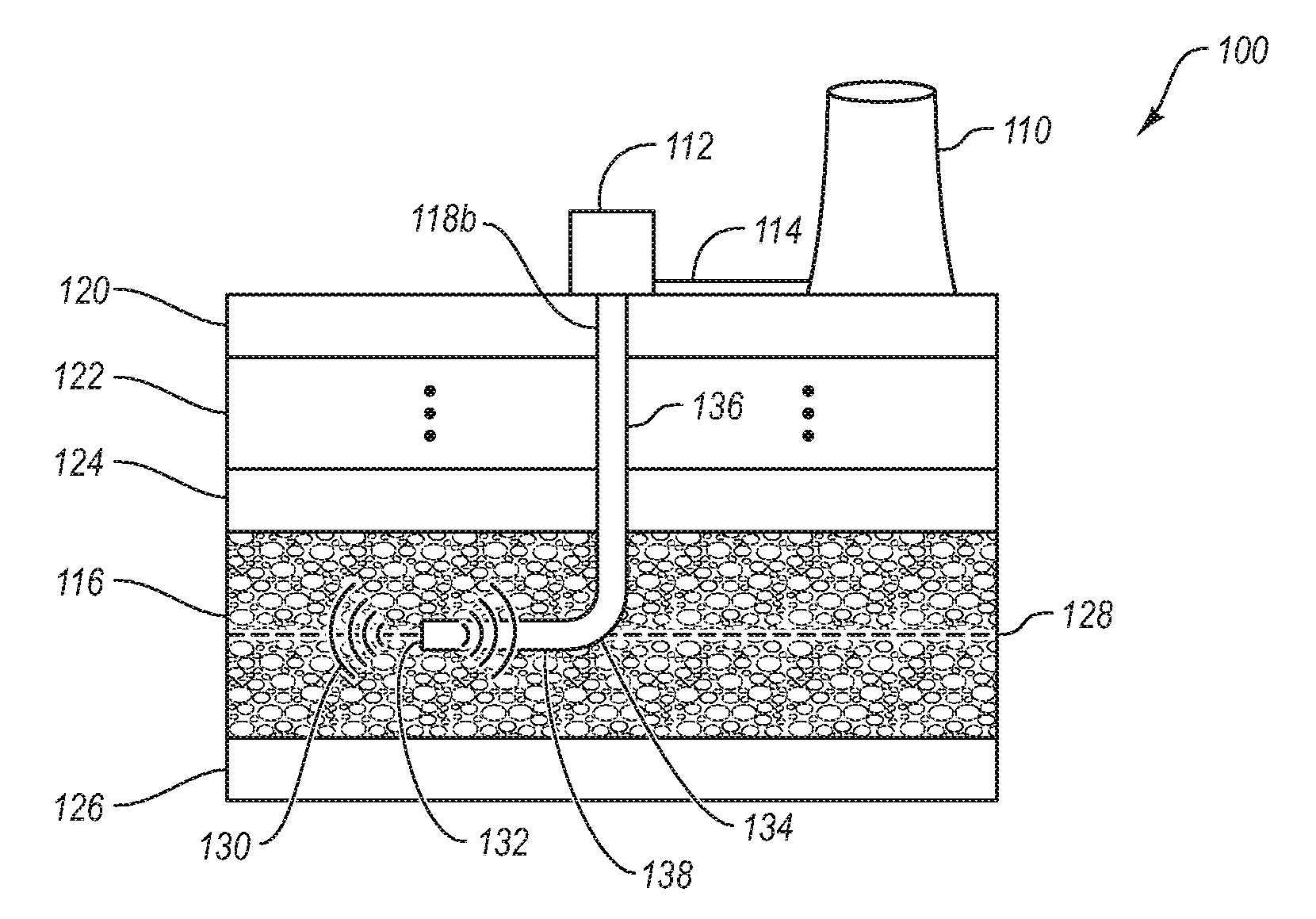
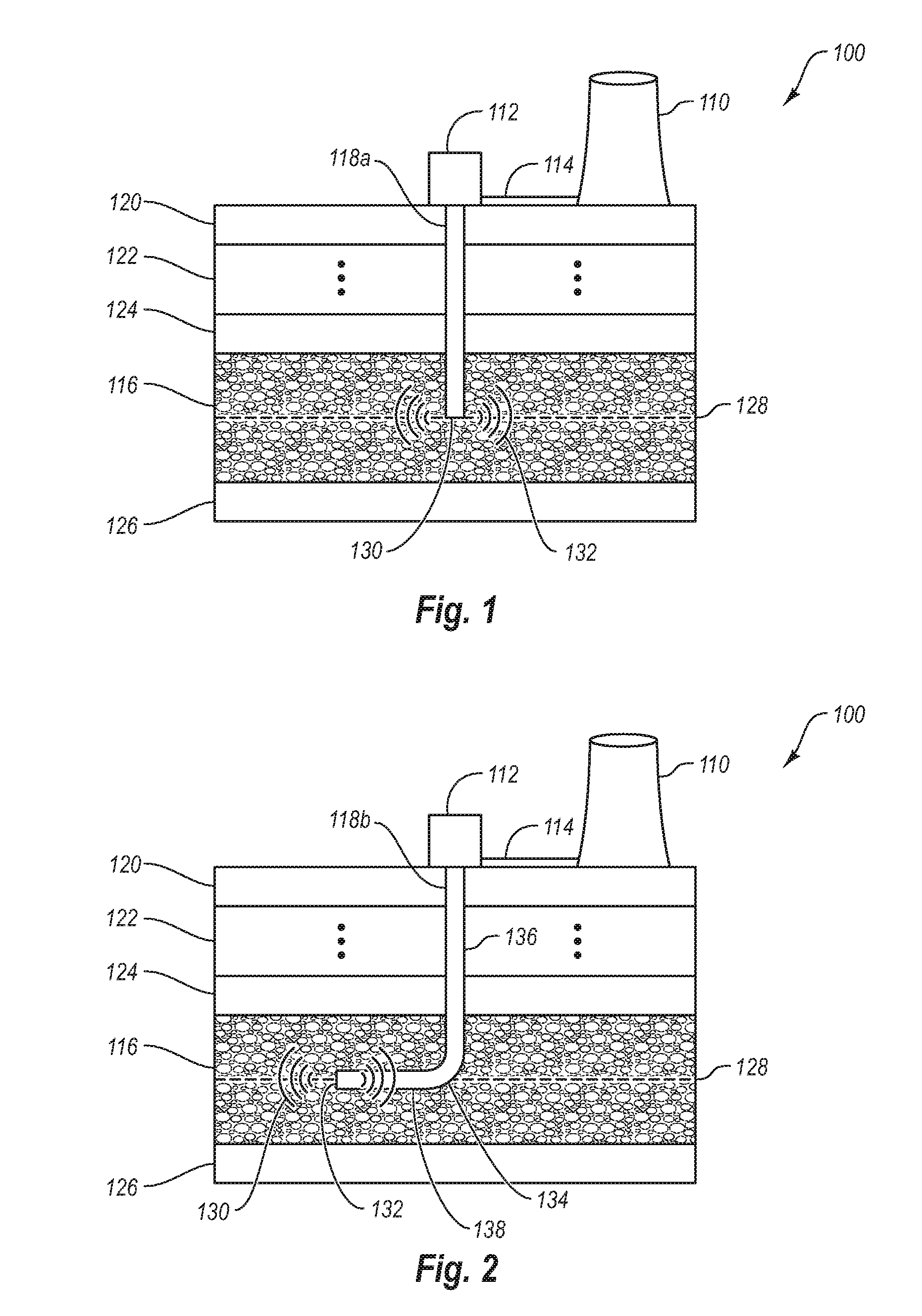
[0014]In one embodiment, lateral dispersion of the CO2 stream into the water of the aquifer is achieved by drilling a horizontal well and injecting the CO2 stream into the to horizontal well. Forming a horizontal well in a rock formation is known in the art of oil drilling. Horizontal drilling has been used in crude oil exploration to overcome problems in pumping oil, particularly viscous oils. (see e.g, U.S. Pat. No. 4,535,845, which is hereby incorporated herein by reference). As used in the methods disclosed herein, the horizontal well allows the CO2 stream to be dispersed throughout the porous rock as it is injected into the aquifer, which causes the CO2 stream to flow up through a significant percentage of the porous rock as compared to a vertical well.
[0016]In one embodiment, the density of the CO2 stream is selected by pumping a liquid CO2 stream to a pressure sufficient to give the CO2 stream a density that is about the same or greater than the density of the water at the point of injection. Selecting a density that is about the same or greater than the density of the water at the point of injection prevents the CO2 stream from rapidly accumulating at the top of the aquifer. Because the CO2 stream is dense, it will float at the level of injection and / or sink. Thus, as the CO2 stream is continually or semi-continuously injected into the aquifer, the CO2 stream diffuses laterally and horizontally. As the CO2 flows through the porous rock, it becomes trapped in the interstitial pores. By selecting a density that is about the same or greater than the aquifer fluid density at the place of injection, the CO2 stream can remain dispersible in the aquifer as it extends laterally until it flows into an interstitial pore, where it becomes permanently trapped or trapped until it dissolves in the surrounding fluid.
[0017]The majority of the CO2 in the injected CO2 stream is not dissolved in the water in to this system. The absorption of the CO2 into the water is small because of the low solubility of CO2 in water. Typically less than 0.1 vol % of an injected carbon dioxide stream will be dissolved in water immediately after injection. While some of the carbon dioxide may be dissolved in the water during the process described herein, a significant percentage of the carbon dioxide is sequestered in the interstitial pores of the aquifer. Trapping CO2 in the interstitial pores of an aquifer allows a much larger percentage of the CO2 stream to be stably sequestered in an aquifer compared to methods where the CO2 is dissolved in the aquifer.

Problems solved by technology

The aquifer is typically a saline aquifer due to low economic value of saline water.
However, fresh water aquifers can also be used, though this may not be advisable because of the high-value alternative uses of fresh water.

Method used


Image

  • Methods for stable sequestration of carbon dioxide in an aquifer
  • Methods for stable sequestration of carbon dioxide in an aquifer
  • Methods for stable sequestration of carbon dioxide in an aquifer

Examples


Embodiment Construction

I. Introduction

[0023]The methods disclosed herein relate to sequestering carbon dioxide in an aquifer by trapping the CO2 in interstitial pores of the aquifer in addition to dissolving the CO2 in the fluid. Trapping the CO2 in the interstitial pores of the aquifer stabilizes the CO2 from essential the time of injection, preventing the sequestered CO2 from escaping back to the surface, and greatly increases the storage capacity of the aquifer compared to fluid dissolution alone.

[0024]For purposes of this invention, a “CO2 stream” as used herein refers to a fluid with a substantially higher concentration (e.g., greater than 1.0 vol %) of carbon dioxide compared to “naturally existing” atmospheric air, which has less than about 0.04 vol % carbon dioxide. However, in most cases a much higher concentration of CO2 is desired do avoid the expense associated with sequestering gases other than CO2.

[0025]For purposes of the present invention, the term “horizontal well” refers to a well shaft ...


PUM

PropertyMeasurementUnit
vol %aaaaaaaaaa
diameteraaaaaaaaaa
thicknessaaaaaaaaaa

Abstract

The methods disclosed herein relate to sequestering carbon dioxide in an aquifer by trapping the CO2 in interstitial pores of the aquifer. Trapping the CO2 in the interstitial pores of the aquifer prevents the sequestered CO2 from escaping back to the surface and allows a much larger percentage of a CO2 to be stably sequestered compared to techniques that rely on dissolving the CO2 to achieve stable sequestration.

Description

CROSS-REFERENCE TO RELATED APPLICATIONS[0001]This application is a continuation of PCT Application serial number PCTUS2009 / 036089, entitled METHODS FOR STABLE SEQUESTRATION OF CARBON DIOXIDE IN AN AQUIFER filed Mar. 4, 2009, which claims the benefit of U.S. Provisional Application No. 61 / 068,129, filed on Mar. 4, 2008, entitled FOSSIL AND BIOMASS POWER SYSTEMS WITH STABLE CO2 SEQUESTRATION both of which are hereby incorporated herein by reference in their entiretyTHE FIELD OF THE INVENTION[0002]The present invention relates to methods for sequestering carbon dioxide in an aquifer.THE RELEVANT TECHNOLOGY[0003]The need to control CO2 emissions on a global scale is widely recognized. Electric power generation plants, which combust fossil fuels to create power, provide an excellent opportunity to mitigate man-made CO2 emissions. In North America, coal is the primary fuel used for electric power generation.[0004]One of the control strategies proposed for CO2 capture / sequestration involve...

Claims


Application Information

Patent Timeline
Patent Type & Authority Patents(United States)
IPC IPC(8): E21B43/16
CPCB01D53/62E21B41/0064B01D2257/504B65G5/005Y02C10/04Y02C10/14Y02P70/30Y02P70/10Y02A50/20Y02C20/40
Inventor BAXTER, LARRY L.
Owner U S BANK TRUST CO NAT ASSOC
Learn More