
Mitral valve cerclarge annuloplasty appratus and method thereof

a technology of mitral valve and annuloplasty appratus, which is applied in the field of mitral valve cerclage annuloplasty devices and techniques, can solve the problems of reducing the effectiveness increasing the stress on the heart, and affecting the flow of blood, so as to improve the mitral valve cerclage annuloplasty apparatus and increase the effectiveness and success of the mitral valve cerclage annuloplasty.

Active Publication Date: 2014-01-21
TAU PNU MEDICAL CO LTD
View PDF2 Cites 6 Cited by
  • Summary
  • Abstract
  • Description
  • Claims
  • Application Information

AI Technical Summary

Benefits of technology

The solution effectively maintains constant tension on the cerclage suture, enhancing the success and effectiveness of the mitral valve cerclage annuloplasty by preventing suture laxity and minimizing tissue damage, thereby improving the treatment of mitral valve regurgitation.

Problems solved by technology

Incomplete opening and closing of the valves cause improper flow of blood, either back flow and / or reduced.
Both can increase stress on the heart.
Such back flow of blood increases stress on the heart which can decrease the heart function and eventually lead to an irregular heart beat or a cardiac arrhythmia.
Although very effective, this open-heart procedure is an invasive high-risk surgery accompanied by a substantial morbidity and mortality.
However, there were technical problems in the previous thesis and patent applications that needed to be solved.
Second, since this tension is maintained with a very fine cerclage suture i.e., 0.014 inch nylon cerclage used in the researches (although thickness may change), it can cause damages on the cardiac tissues where the suture contacts and exerts its pressure.
However, even though the knot was placed at the end of the tissue protective device, a slack of suture remained between the end of the tissue protective device and the knot, so that the proper tension needed on the cerclage was difficult to obtain initially, and due to the remaining excess suture, the cerclage became loose.
In the aforementioned mitral valve cerclage annuloplasty procedure, when the cerclage suture became loose, the tension on the suture decreased thereby reducing its circumferential pressure applied around the MA resulting in a decreased effectiveness of the MVR treatment.

Method used


Image

  • Mitral valve cerclarge annuloplasty appratus and method thereof
  • Mitral valve cerclarge annuloplasty appratus and method thereof
  • Mitral valve cerclarge annuloplasty appratus and method thereof

Examples


Embodiment Construction

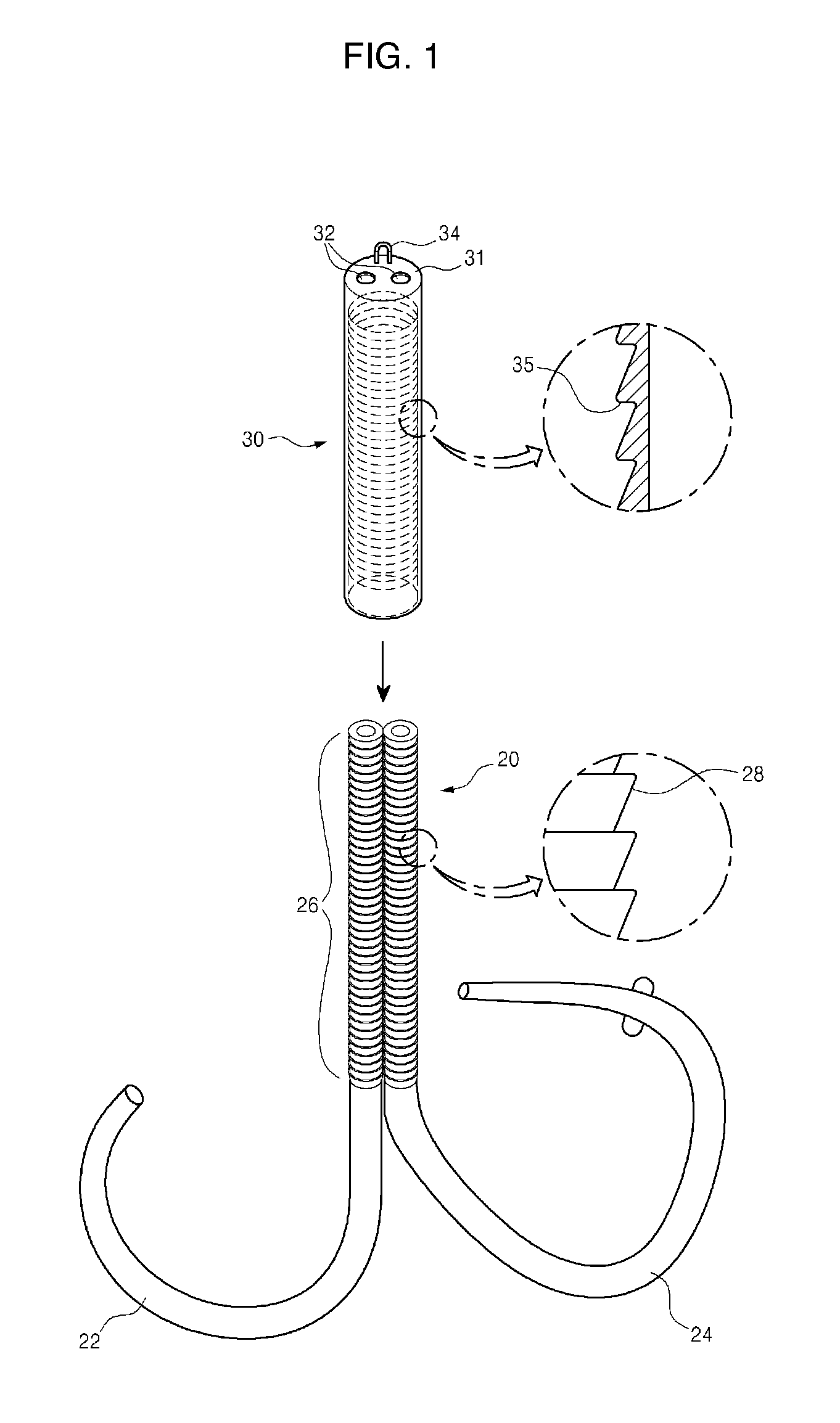
[0035]The detailed disclosure of the mitral valve cerclage annuloplasty apparatus (MVA) comprising a tissue protective device and a hollow cap will be discussed.

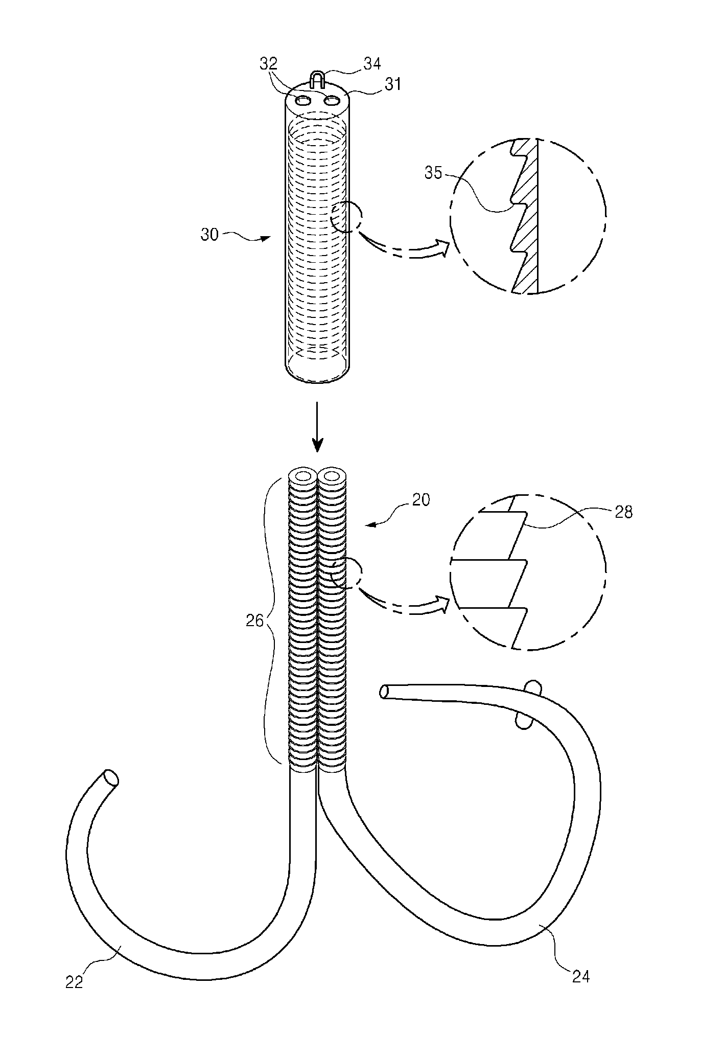
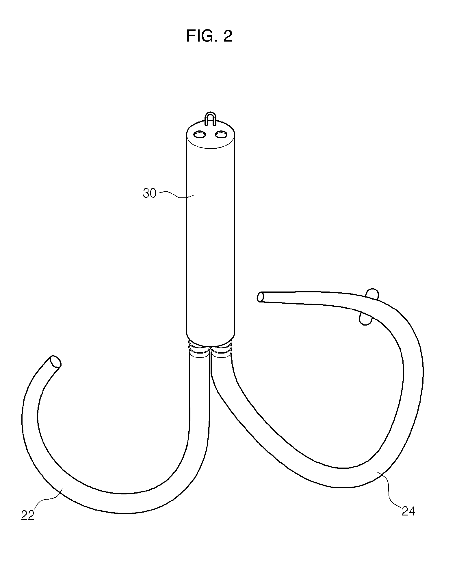
[0036]According to the current invention, FIGS. 1-2 shows the mitral valve cerclage annuloplasty apparatus (MVA) comprising the tissue protective device 20 and the hollow cap 30. FIG. 1 shows the tissue protective device 20 and the hollow cap 30 before they are engaged, and FIG. 2 shows the tissue protective device 20 and the hollow cap 30 in an engaged state. The tissue protective device 20 in the current invention differs from the inventor's previous patent application (#2009-0080708) in that the stem portion of the tissue protective device 20 has a built-in locking bumps 28 ingrained on its outer surface.

[0037]Generally, in a conventional MVA techniques cause tissue damage or erosion to the coronary sinus (“CS”), the tricuspid valve (“TV”) and the intraventricular septum (“IVS”) from a direct cerclage suture to tissue con...


PUM


Abstract

A mitral cerclage annuloplasty apparatus comprises a tissue protective device and a cap device having a cerclage suture disposed within a first protective tube and a second protective tube, the proximal portions of the two tubes being attached side-by-side longitudinally to define a stem portion, the distal portions of the two tubes being separated thereafter, and a cap device that covers the stem portion wherein the stem portion and the cap device interlock, so that once the cerclage suture is knotted on the outer surface of the cap device, cap device can be pulled outwardly to enhance and maintain tension applied to the mitral annulus thus successfully treating the mitral regurgitation.

Description

CROSS-REFERENCE TO RELATED APPLICATIONS[0001]This application is a continuation-in-part of prior application Ser. No. 12 / 631,803, filed Dec. 4, 2009 and claims the benefit of a foreign priority of Korean Patent Application No. 10-2011-0080392, filed Aug. 12, 2011, which is incorporated herein in its entirety.FIELD OF THE DISCLOSURE[0002]The present disclosure relates to mitral valve cerclage annuloplasty devices and techniques in which during the final stage of cerclage annuloplasty procedure, a proper tension is applied and maintained safely on the cerclage sutures then firmly secured by using a knot tightening and securing device.BACKGROUND OF THE INVENTION[0003]The heart is the center of human circulatory system that pumps blood through our body. It is a muscle that pumps the blood only in one direction. In order for the heart to effectively maintain this unidirectional flow of blood, it must have properly functional valves that prevent back flow through its system, or regurgitat...

Claims


Application Information

Patent Timeline
Patent Type & Authority Patents(United States)
IPC IPC(8): A61F2/24
CPCA61F2/2466A61B2017/0496A61F2/2451A61B17/0487
Inventor KIM, JUNE-HONG
Owner TAU PNU MEDICAL CO LTD
Learn More