
System to measure the absorptive capabilities of porous materials used in oil spill remediation

a technology of porous materials and absorption capabilities, applied in the field of oil spill remediation and cleanup techniques, can solve the problems of difficult prevention measures, inability to effectively clean up, and inability to effectively implement bioremediation,

Inactive Publication Date: 2014-01-21
CHAKRADHAR VINEEL
View PDF7 Cites 10 Cited by
  • Summary
  • Abstract
  • Description
  • Claims
  • Application Information

AI Technical Summary

Benefits of technology

Enables the rapid identification of efficient porous materials for specific oil spill scenarios, providing a quantitative measure of absorption capacity and rate, and accelerates the design of materials tailored for oil spill remediation.

Problems solved by technology

The onset of these spills is extremely difficult, if not impossible, to predict in advance, and thus preventative measures are tough to institute.
Bacteria are living organisms, and they can perish due to unfavorable environmental conditions (bad weather, for example).
Furthermore, bacteria remove oil extremely slowly.
In many cases, the process of oil removal is too slow for bioremediation to be an effective cleanup technique.
However, with time, the oil begins to form channels underneath and through crevices in the booms, and the oil begins to spread beyond the booms.
Dispersants cause problems though because the oil is not really removed—it has simply been integrated with the environment underneath, just removed from the surface.
After some time, the oil integrated into the water harms the local ecosystems, and affects the economies that depend on the welfare of those aquatic ecosystems such as the fishing industry.
Also, the dispersants are man-made chemicals that can be harmful to the aquatic ecosystems.
The problem with skimming is that the technology only functions optimally in calm weather—if the water is turbulent and the environment windy, which in fact is extremely characteristic of the Gulf area in which the Deepwater Horizon oil spill took place, the surface is not necessarily just oil because the turbulence serves to “break” the sheet of oil on the top, and then the skimmer will then be skimming and filtering a mixture of oil and water.
Clearly, due to the limitations of current methods available for oil spill remediation, there is a massive effort to discover new and different methods [4, 5, 6, 7, 8].
However, as with any new and aspiring technology, there are no systems available for measuring the efficacy of these porous materials in oil spill cleanup.
Note that most porous materials in the industry, including sol-gels, were not designed for use in oil spill remediation.
However, a test where the porous material and the mixture are both stationary is not useful to identify porous materials that can be effective in oil-spill cleanups.
Low-cost systems that can quickly test the oil-absorbing capability of porous materials by taking into account the environmental conditions around the oil spill have not been developed.

Method used


Image

  • System to measure the absorptive capabilities of porous materials used in oil spill remediation
  • System to measure the absorptive capabilities of porous materials used in oil spill remediation
  • System to measure the absorptive capabilities of porous materials used in oil spill remediation

Examples


Embodiment Construction

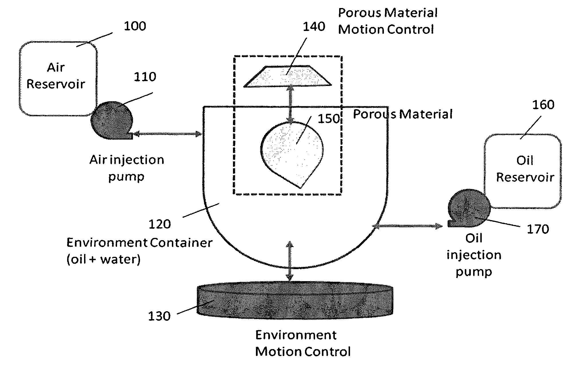
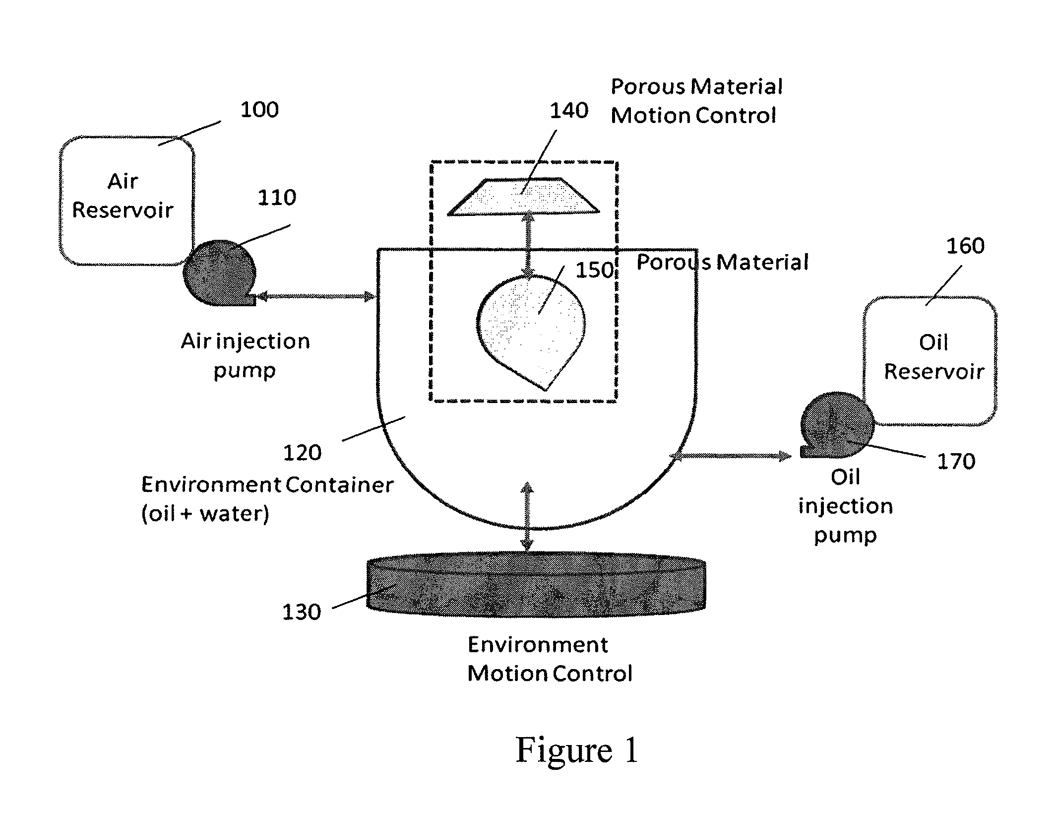
[0025]FIG. 1 shows the block diagram of the proposed testing system. The full system has five subsystems: blocks 100 and 110 make up the wind injection system, blocks 120 and 130 make up the environmental motion control system, blocks 140 and 150 make up the porous material motion system, and blocks 160 and 170 make up the oil injection system. The fifth sub-system called the environment container 120 contains the mixture of water and oil. The oil injection system and the air injection system directly funnel into the environment container. A separate motion control system 130 is used to create movement of the mixture in the environment container. The porous material moves inside the environment container. Depending on the motion vectors of the porous material and the mixture in the environment container, the porous material may be fully or partially submerged in the oil and water mixture.

[0026]We describe a typical use case scenario of the proposed testing system. The testing proces...


PUM

PropertyMeasurementUnit
oleophilicaaaaaaaaaa
absorbanceaaaaaaaaaa
movementaaaaaaaaaa

Abstract

Traditional porous material testing does not provide a measure of how well the porous material will perform in oil spill conditions. We disclose a new system that can analyze and determine the absorptive capability and oil-selectivity of a porous material in a moving mixture of oil and water, under different environmental conditions of pressure and wind. Our system allows the porous material under test and the mixture of oil and water to experience complex motion trajectories, and we measure the absorption capacity as well as the rate of oil absorption under different environmental conditions.

Description

BACKGROUND[0001]1. Technical Field[0002]This invention relates to oil spill remediation and cleanup techniques where porous materials with oil-absorbing capabilities can be widely utilized.[0003]2. Description of the Related Art[0004]From Exxon-Valdez in 1989 to the more recent Deepwater Horizon in 2010, oil spills rank among the worst human-induced disasters our earth can face both environmentally and economically. The onset of these spills is extremely difficult, if not impossible, to predict in advance, and thus preventative measures are tough to institute. The next best thing is to minimize the lasting effects of oil spills by using effective remediation methods.[0005]Right now, there are five major oil spill remediation methods that are in wide use: bioremediation, containment, dispersion, in situ burning, and skimming [1, 2, 3, 4].[0006]Bioremediation involves using bacteria as well as other microorganisms that consume oil as part of their daily life to clean up the oil spill....

Claims


Application Information

Patent Timeline
Patent Type & Authority Patents(United States)
IPC IPC(8): G01N5/02
CPCG01N5/02
Inventor CHAKRADHAR, VINEEL
Owner CHAKRADHAR VINEEL
Learn More