System and method for reducing the noise of pusher type aircraft propellers

a propeller and pusher technology, applied in the direction of airflow influencers, fuselages, transportation and packaging, etc., can solve the problems of engine muffle, uav noise can be detected by noise, and no formal department of defense reporting procedures have been established to track suas flight hours

Active Publication Date: 2014-01-07
AURORA FLIGHT SCI CORP
View PDF14 Cites 18 Cited by
  • Summary
  • Abstract
  • Description
  • Claims
  • Application Information

AI Technical Summary

Benefits of technology

[0012]The present application is directed to embodiments for reducing the noise generated by a (preferably UAV) pusher propeller, thereby enabling an aircraft to retain the advantages of its UAV configurations, while yielding acoustic performance similar to that of the more traditional tractor propeller.
[0013]In a first aspect, the present invention is directed to a system for reducing pusher propeller noise. The system comprises: an airfoil-shaped flight surface; a scoop enabled to route boundary layer air from said flight surface; a suction device enabled to provide a suction force (preferably, pressure) wherein said scoop routes boundary layer air from said flight surface to said suction device; and a slot (or other opening) in said flight surface for applying said suction force.
[0014]In a second aspect, the present invention is directed to a method for reducing pusher propeller noise. The method comprises the steps of: routing boundary layer air from an airfoil-shaped flight surface via a scoop; applying a suction force (preferably, pressure) via a slot (or other opening) in said flight surface; and providing said suction force via a suction device wherein said scoop routes boundary layer air from said flight surface to said suction device.
[0015]In a third aspect, the present invention is directed to an airfoil-shaped flight surface for reducing pusher propeller noise. The airfoil-shaped flight surface comprises: a scoop enabled to route boundary layer air; a suction device enabled to provide a suction force (preferably, pressure) wherein said scoop routes boundary layer air from said flight surface to said suction device; and a slot (or other opening) in said flight surface for applying said suction force.

Problems solved by technology

However, due to the recent development and use of SUAS in combat, no formal Department of Defense reporting procedures have been established to track SUAS flight hours.
However, despite these measures, a UAV can often be detected by its noise.
A first source of noise is the engine; however, the engine may be muffled using known technology.
Although these tail pipe designs may help to alter the noise patterns, they are not true mufflers.
Although these solutions typically result in power loss and weight increase, the net operational advantage of a quieter engine often makes the endeavor worthwhile.
Apart from engine noise, a second, and rather substantial, source of noise is created by the aircraft propellers which, unlike an engine, cannot be easily muffled.
While some UAVs use jet propulsion, many UAVs are still propeller-driven and can therefore generate a significant amount of noise when a wake (typically formed by upstream flight surfaces) encounters a propeller, thereby increasing external noise levels.
In fact, the noise emission of a UAV propeller (e.g., a pusher propeller) can be so strong that the propeller noise alone may be able to attract attention from ground personnel during a mission, thereby fomenting unwanted attention or a potential attack on the UAV.

Method used


Image

  • System and method for reducing the noise of pusher type aircraft propellers
  • System and method for reducing the noise of pusher type aircraft propellers
  • System and method for reducing the noise of pusher type aircraft propellers

Examples


Embodiment Construction

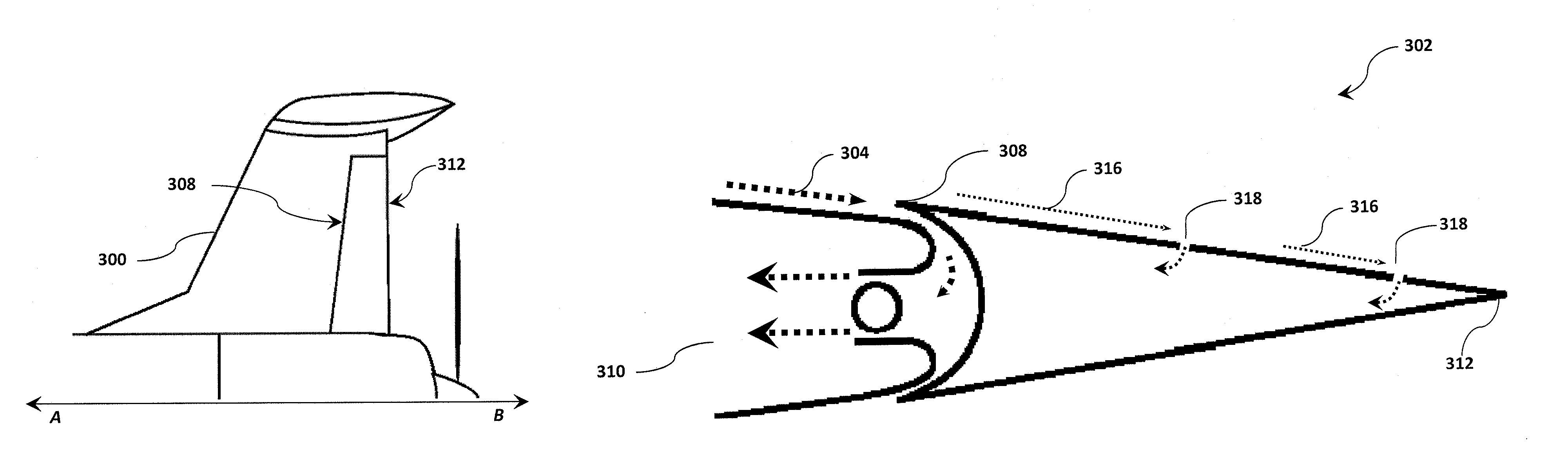
[0034]Embodiments of the present invention will be described hereinbelow with reference to the accompanying drawings. In the following description, well-known functions or constructions may not be described in cumbersome detail because such would obscure the invention in unnecessary detail. The present invention discloses a system and method for eliminating, or greatly reducing, the wake created by flight surfaces upstream of the propeller, thereby reducing propeller noise.

[0035]A propeller blade is an airfoil and, like a wing, it will generate an aerodynamic force much the same way. It has a leading edge and a trailing edge, a camber, and a chord line. The cambered side is called the blade back and the flatter side the blade face. The angle which the chord makes to the plane of rotation is the blade angle. A propeller having one or more propeller blades is rotated by an engine to create thrust and move the aircraft forward. There are multiple methods for reducing noise attributed t...


PUM


Abstract

A system and method for reducing the noise penalty of a pusher propeller, allowing an aircraft to retain its advantages for UAV configurations, while allowing acoustic performance similar to that of a tractor propeller by reducing, or eliminating, propeller noise emissions. The system and method provide an airfoil-shaped flight surface with (i) a scoop configured to route boundary layer air and associated wake from said flight surface, and (ii) a suction device configured to provide a suction pressure, wherein the scoop routes boundary layer air from the flight surface to the suction device via an opening in the flight surface.

Description

TECHNICAL FIELD[0001]The present invention relates to a method and apparatus for suppressing noise associated with a propeller-driven aircraft. Specifically, the present invention relates to suppression and reduction of aerodynamic noise generated when a wake encounters an aerial vehicle's pusher propeller.BACKGROUND[0002]An unmanned aerial vehicle (UAV) is an aircraft enabled to be flown remotely by a pilot, a navigator, or under computer control, typically without a human crew on board, and is often used for military applications. For the purposes of this application, a UAV is defined as an aircraft being capable of controlled, sustained, level flight and powered by a jet or reciprocating engine (e.g., propeller-driven). In some instances, the acronym UAV has been expanded to UAVS (Unmanned Aircraft Vehicle System), while the FAA (Federal Aviation Administration) has adopted the acronym UAS (Unmanned Aircraft System) to reflect the fact that these complex systems can include groun...

Claims


Application Information

Patent Timeline
Patent Type & Authority Patents(United States)
IPC IPC(8): B64C1/40
CPCB64C2230/28B64C21/06Y02T50/66B64C2230/14B64D27/12B64D27/06Y02T50/166Y02T50/10Y02T50/60
Inventor DRELA, MARKGUNDLACH, JOHNPARKS, ROBERTEHRMANTRAUT, ADAM SCOTT
Owner AURORA FLIGHT SCI CORP
Why Eureka
Try Eureka