Position controller for image-stabilizing insertable/removable optical element

a technology of positioning controller and optical element, which is applied in the field of positioning controller of optical element, can solve the problems of large size of the driven member that holds the rotatable frame and complex shape of the driven member, and achieve the effect of reducing image shak

Inactive Publication Date: 2013-12-31
HOYA CORP
View PDF7 Cites 0 Cited by
  • Summary
  • Abstract
  • Description
  • Claims
  • Application Information

AI Technical Summary

Benefits of technology

[0006]The present invention has been devised in view of the above-mentioned drawbacks and provides a small-sized (compact) position controller for controlling the position of an optical element which can be driven within an anti-shake driving range to reduce image shake in a ready-to-photograph state and which can also be removed from the anti-shake driving range.
[0007]According to an aspect of the present invention, a position controller is provided, for an image-stabilizing optical element which is provided in a photographing optical system which moves between a ready-to-photograph state and an accommodated state in which no pictures are taken, the position controller including an advancing / retracting member movable in an optical axis direction of the photographing optical system, wherein the advancing / retracting member is moved between a first position at which the photographing optical system is in the ready-to-photograph state and a second position at which the photographing optical system is in the accommodated state; an anti-shake frame supported by the advancing / retracting member to be movable along a plane orthogonal to the optical axis; an insertable / removable frame which holds the optical element and is supported by the anti-shake frame to be movable between an insertion position in which the optical element is positioned on the optical axis and a removed position in which the optical element is removed from the optical axis; an anti-shake drive mechanism which drives the anti-shake frame to perform an image-stabilizing operation in accordance with vibrations applied to the photographing optical system; and a removal drive mechanism which imposes no limitations on movements of the anti-shake frame and the insertable / removable frame that are caused by the anti-shake drive mechanism in the ready-to-photograph state, and which imparts a component force that makes the insertable / removable frame move to the removed position from a moving force of the advancing / retracting member to move the anti-shake frame in a direction toward the removed position in association with the insertable / removable frame when the advancing / retracting member moves in the optical axis direction from the first position to the second position.
[0016]According to the present invention, the anti-shake frame is moved (driven) in a direction toward the removed position of the insertable / removable frame by the movement of the insertable / removable frame to the removed position so that the amount of movement of the insertable / removable optical element to remove the insertable / removable optical element from a position on an optical path (the optical axis) is shared between the insertable / removable frame and the anti-shake frame, and accordingly, the position controller for the insertable / removable optical element can be miniaturized to a greater degree than that in the case where the aforementioned amount of movement of the insertable / removable optical element is secured solely by the insertable / removable frame.

Problems solved by technology

According to this structure, the amount of rotation of the rotatable frame corresponds to the removing amount of the lens element; however, if the amount of rotation of the rotatable frame is great, the driven member that holds the rotatable frame becomes great in size or the shape of the driven member becomes complicated.

Method used


Image

  • Position controller for image-stabilizing insertable/removable optical element
  • Position controller for image-stabilizing insertable/removable optical element
  • Position controller for image-stabilizing insertable/removable optical element

Examples


Embodiment Construction

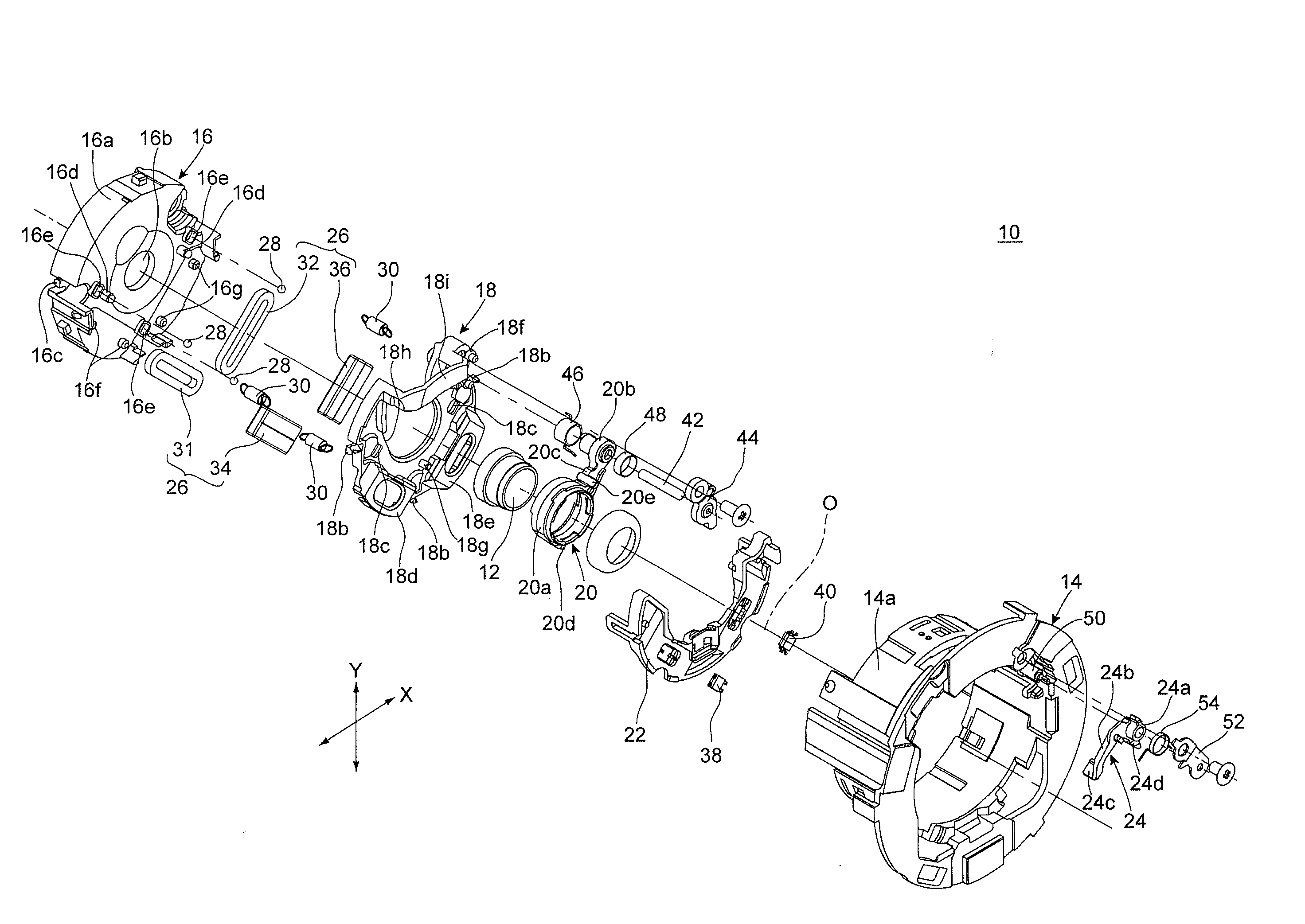
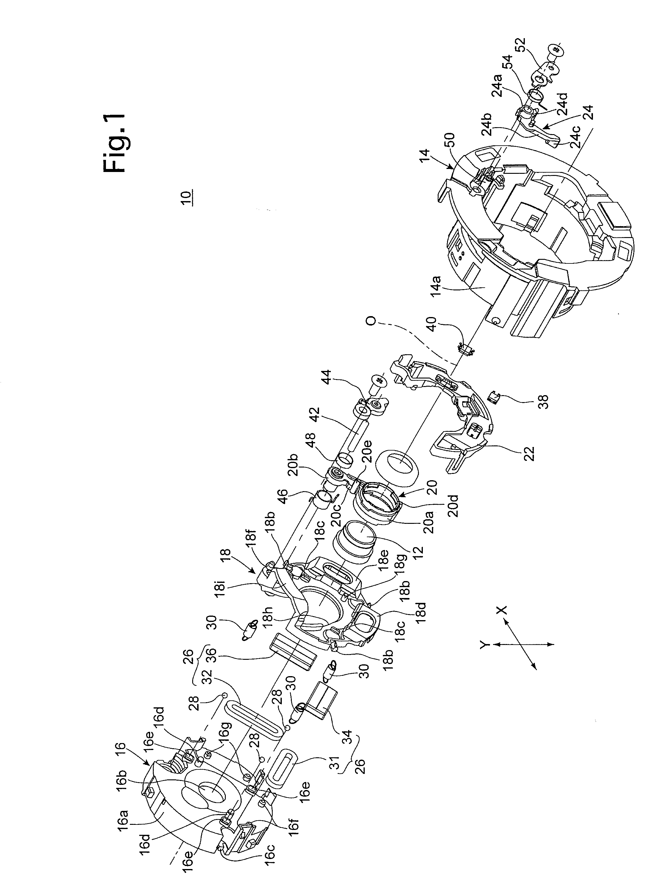
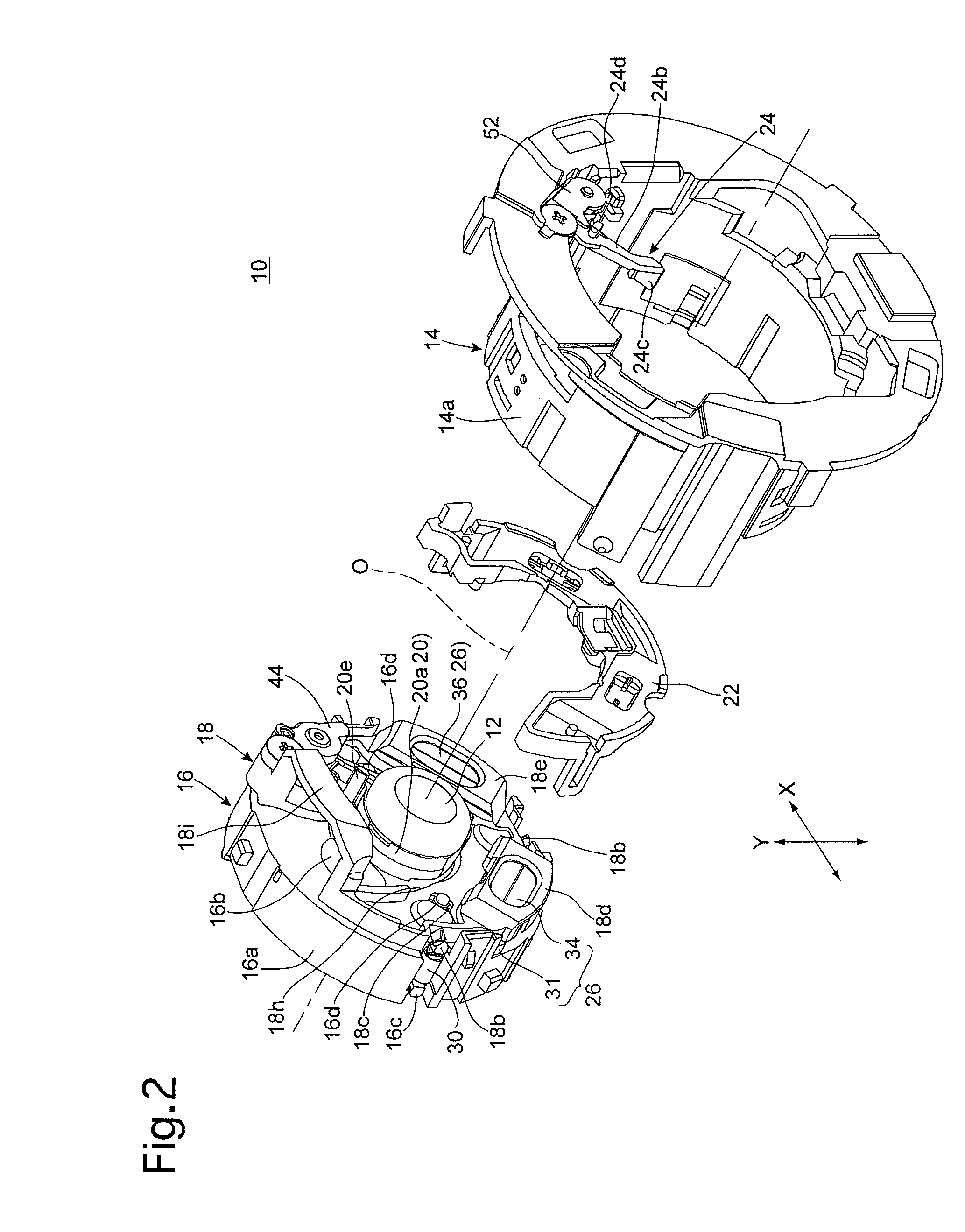
[0033]An anti-shake lens unit 10 shown in FIGS. 1 through 3 supports an insertable / removable image-stabilizing lens (insertable / removable image-stabilizing optical element) 12 which constitutes a part of a photographing optical system of a lens barrel of a camera. As shown in FIG. 1, the anti-shake lens unit 10 is provided with a linear moving ring (advancing / retracting member) 14, and is provided in the linear moving ring 14 with a shutter unit (advancing / retracting member) 16, an anti-shake frame 18, an insertable / removable frame 20, a sensor holder 22, a removal drive lever (removal drive mechanism / rotational relay member) 24 and an anti-shake drive actuator (anti-shake drive mechanism) 26.

[0034]Although the overall structure of the lens barrel in which the anti-shake lens unit 10 is incorporated is not shown in the drawings, the linear moving ring 14 is supported inside the lens barrel thereby in a manner to be linearly movable in a direction along a photographing optical axis O...


PUM


Abstract

A position controller for an image-stabilizing optical element in a optical system includes an advancing / retracting member; an anti shake frame supported by the advancing / retracting member and movable along a plane orthogonal to the optical axis; an insertable / removable frame holding the optical element and supported by the anti-shake frame to be movable between insertion and removed positions; an anti shake drive mechanism which drives the anti shake frame to perform an image-stabilizing operation; and a removal drive mechanism which imposes no movement limitations on the anti shake frame and the insertable / removable frame in a ready-to-photograph state, and which imparts a component force that moves the insertable / removable frame to the removed position in association with the insertable / removable frame when the advancing / retracting member moves to an accommodated position.

Description

BACKGROUND OF THE INVENTION[0001]1. Field of the Invention[0002]The present invention relates to a position controller for an optical element which can be moved to correct image shake and removed to a position outside an anti-shake driving range of the optical element.[0003]2. Description of the Related Art[0004]There has been an increasing number of optical devices such as cameras which are equipped with an anti-shake mechanism (image shake correcting mechanism / image stabilizing mechanism) that moves a specific optical element such as a lens element or an image sensor (image pickup device) in a plane orthogonal to an optical axis of an optical system to reduce (correct) image shake. In Japanese Unexamined Patent Publication 2007-101993, a technique for removing (radially retracting) an image-stabilizing optical element to a position outside an anti-shake driving range (to a position off an optical axis of the optical system) when an optical device that incorporates the anti-shake m...

Claims


Application Information

Patent Timeline
Patent Type & Authority Patents(United States)
IPC IPC(8): H04N5/228
CPCG03B2205/0092G03B2205/0069G03B2205/0015G02B27/646G03B5/00G03B2205/00
Inventor SUZUKA, SHINYA
Owner HOYA CORP
Why Eureka
Try Eureka