Fiber optic assemblies having connectors with recessed optical fibers

a fiber optic and connector technology, applied in the field of fiber optic assemblies, can solve problems such as damage and/or debris, and achieve the effect of reducing the susceptibility to damage and optical attenuation

Inactive Publication Date: 2013-12-31
CORNING OPTICAL COMM LLC
View PDF12 Cites 0 Cited by
  • Summary
  • Abstract
  • Description
  • Claims
  • Application Information

AI Technical Summary

Benefits of technology

[0006]Embodiments disclosed in the detailed description are directed to fiber optic assemblies having a plurality of optical fibers in a connector including a ferrule. The ferrule has a front end face and a plurality of bores with the plurality of optical fibers being disposed within one of the respective plurality of bores. The fiber optic assemblies are advantageous since the plurality of optical fibers are recessed from the front end face of the ferrule for inhibiting physical contact of the plurality of optical fibers when mated. Consequently, the fiber optic assemblies are suited for hundreds or thousands of connections and disconnections (i.e., mating cycles) with reduced susceptibility from damage and optical attenuation caused by dirt, debris and the like, thereby making the fiber optic assemblies suitable for devices requiring large numbers of matings such as consumer electronic devices. Moreover, the fiber optic assemblies do not allow physical contact between the fibers that can cause damage and / or debris for the same.

Problems solved by technology

Moreover, the fiber optic assemblies do not allow physical contact between the fibers that can cause damage and / or debris for the same.

Method used


Image

  • Fiber optic assemblies having connectors with recessed optical fibers
  • Fiber optic assemblies having connectors with recessed optical fibers
  • Fiber optic assemblies having connectors with recessed optical fibers

Examples


Embodiment Construction

[0015]Reference will now be made in detail to certain embodiments, examples of which are illustrated in the accompanying drawings, in which some, but not all features are shown. Indeed, embodiments disclosed herein may be embodied in many different forms and should not be construed as limited to the embodiments set forth herein; rather, these embodiments are provided so that this disclosure will satisfy applicable legal requirements. Whenever possible, like reference numbers will be used to refer to like components or parts.

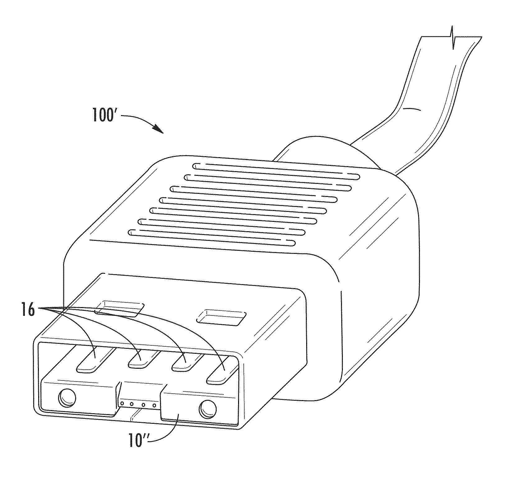
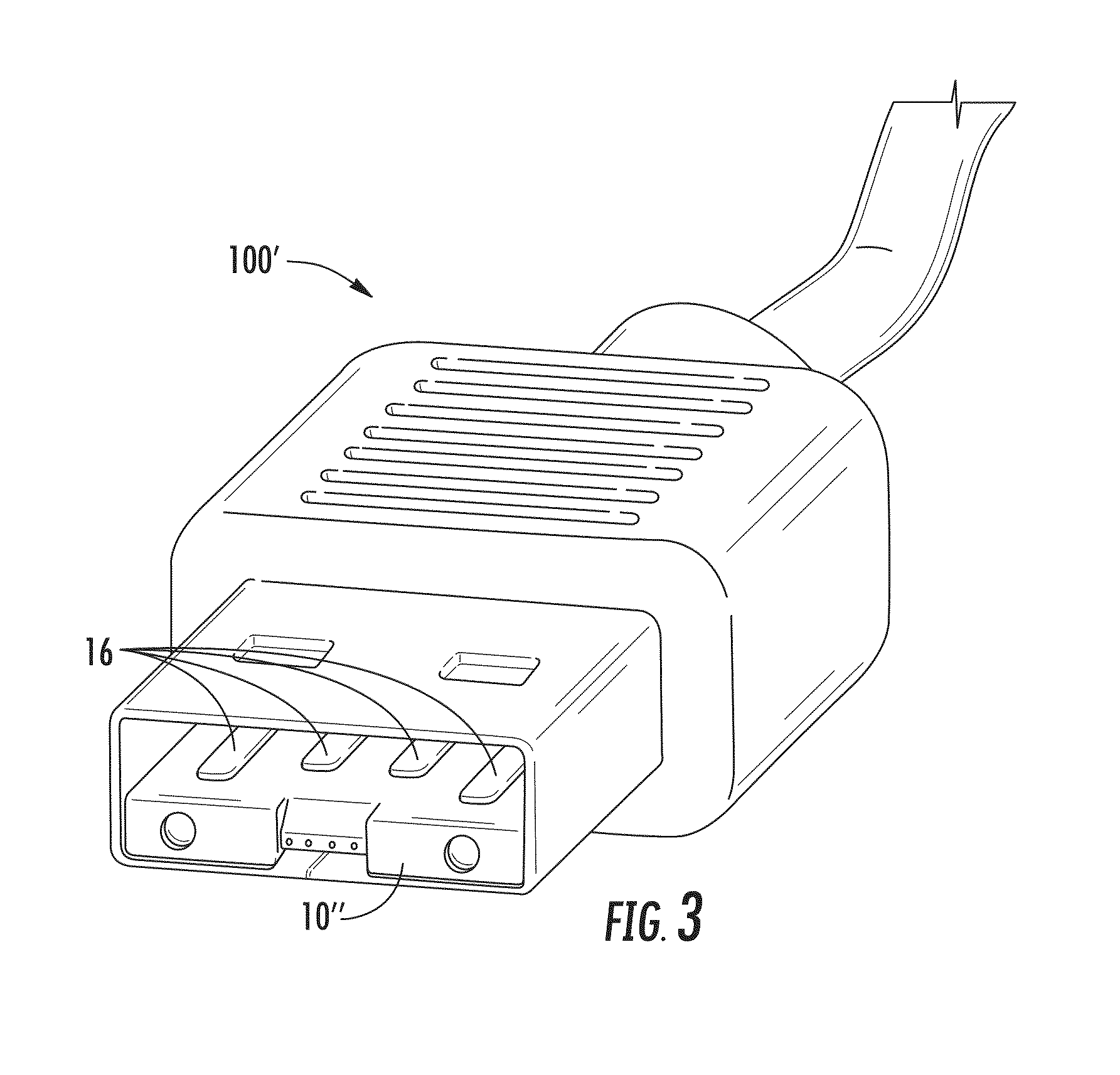
[0016]Embodiments disclosed in the detailed description include fiber optic connectors and fiber optic assemblies such as cable having fiber optic connectors. The concepts disclosed herein are shown with respect to explanatory embodiments and may be used with suitable multi-fiber connectors on cables or consumer devices / electronics intended for a large number of mating cycles over their lifetime.

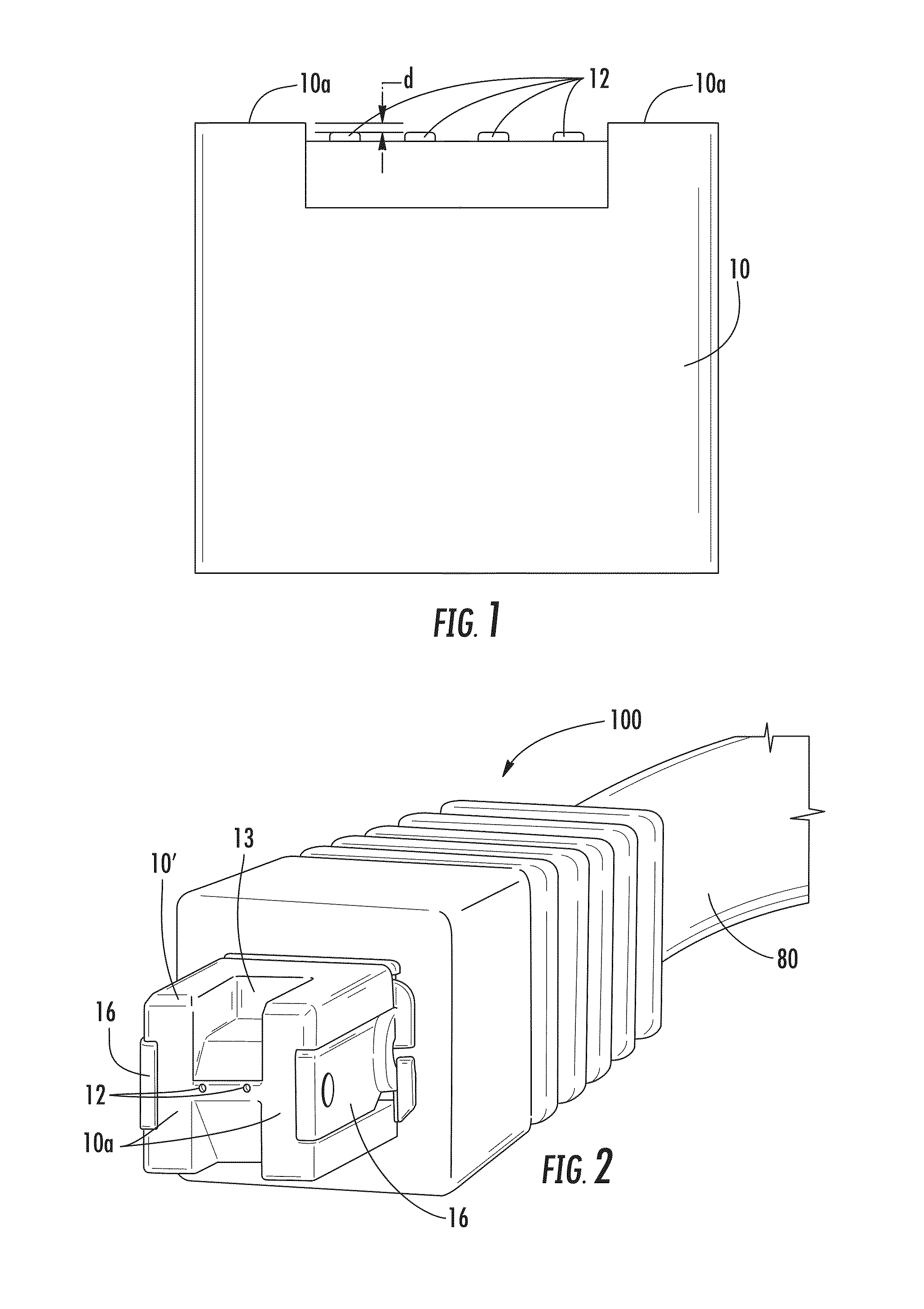
[0017]FIG. 1 depicts a portion of a representative fiber optic assem...


PUM


Abstract

Fiber optic assemblies including a plurality of optical fibers in a connector having a ferrule are disclosed. The ferrule has a front end face and a plurality of bores with the plurality of optical fibers being disposed within one of the respective plurality of bores. The fiber optic assemblies have the plurality of optical fibers recessed from the front end face of the ferrule by a suitable distance to inhibit physical contact of the plurality of optical fibers when mated with a complementary connection. Consequently, the fiber optic assemblies are suited for hundreds or thousands of connections and disconnections (i.e., mating cycles) with reduced susceptibility from damage and / or optical attenuation caused by dirt, debris and the like as expected with the consumer electronic / device environments.

Description

RELATED APPLICATIONS[0001]The present application claims priority to U.S. Ser. No. 61 / 328,142 filed on Apr. 26, 2010 and entitled “FIBER OPTIC ASSEMBLIES HAVING CONNECTORS WITH RECESSED OPTICAL FIBERS”, the contents of which are incorporated by reference.BACKGROUND[0002]The disclosure relates to fiber optic assemblies used for making repeated optical connections and disconnections. Specifically, the disclosure is directed to fiber optic assemblies having optical fibers that are recessed from an end face of a ferrule for allowing large numbers of connections and disconnections (i.e., matings) while providing suitable optical performance over its lifetime.[0003]Benefits of optical fiber include extremely wide bandwidth and low noise operation. Because of these advantages, optical fiber is increasingly is used for a variety of applications such as transmission of broadband voice, video, and data transmission. Conventional fiber optic assemblies typically use a ferrule in the connector ...

Claims


Application Information

Patent Timeline
Patent Type & Authority Patents(United States)
IPC IPC(8): G02B6/36
CPCG02B6/3885G02B6/3847G02B6/3817
Inventor HALL, RADAWANISENHOUR, MICAH C.KNECHT, DENNIS M.LUTHER, JAMES P.
Owner CORNING OPTICAL COMM LLC
Why Eureka
Try Eureka