Radio frequency (RF) amplifier utilizing a predistortion circuit and related techniques

a technology of predistortion circuit and radio frequency amplifier, which is applied in the direction of amplifiers, amplifier modifications to reduce noise influence, electrical equipment, etc., can solve the problems that the output signal of the rf amplifier is unacceptable in signal distortion and the distortion cannot be linearized by standard predistortion techniques, so as to improve the rf bandwidth of envelope-tracking transmitters

Inactive Publication Date: 2013-12-17
AURIGA MEASUREMENT SYST
View PDF29 Cites 24 Cited by
  • Summary
  • Abstract
  • Description
  • Claims
  • Application Information

AI Technical Summary

Benefits of technology

[0012]To address this problem, described herein is a technique to eliminate the bandwidth limit imposed by a drain modulator circuit. The technique described herein is referred to as “bandwidth-optimized drain modulation.” With this technique, a drain modulator circuit can operate at a bandwidth lower than an RF signal bandwidth of an amplifier or conversely, the RF amplifier bandwidth can exceed the bandwidth of the drain modulator. This has a great benefit to communication systems, from handheld radios to base stations, where efficiency and bandwidth are both critical. In one aspect, the baseband processor time-aligns a bandwidth-optimized, drain-modulation signaled to an RF signal and then a pre-distortion function generates a compensating value taking into account RF input power, RF output power and drain voltage. The compensating value is then applied to the RF input signal (e.g. through a digital pre-distortion processor) and the drain modulated voltage (e.g. through a drain modulation circuit).
[0014]With this particular arrangement, a bandwidth-optimized drain modulation technique to reduce or even eliminate a bandwidth limit imposed on the RF amplifier by the drain modulation circuit is provided. In state-of-the-art envelope tracking, if the bandwidth of the RF amplifier exceeds the bandwidth of the drain modulation circuit, then the RF amplifier output signal has unacceptable levels of signal distortion. These distortions cannot be linearized by standard predistortion techniques. However, by sampling both the drain signal and the RF output signal and providing drain feedback and RF output feedback signals to a pre-distortion processor, then the distortions can be properly linearized enabling the RF amplifier to operate over a bandwidth which exceeds the bandwidth of the drain modulation circuit (i.e., the RF bandwidth can exceed the bandwidth of the drain modulator). This technique results in an amplifier circuit having improvements in both efficiency and bandwidth compared with prior art systems that have to trade-off one for the other. Such improvements in efficiency and bandwidth have a great benefit to communication systems, from handheld radios to base stations, where efficiency and bandwidth are both critical factors in system design and fabrication.
[0016]In one embodiment, the methods improve the RF bandwidth of envelope-tracking transmitters.
[0025]With this particular arrangement, a method of operating an envelope tracking RF amplifier is provided. By generating a bandwidth optimized drain modulation signal as a function of an input signal, a sampled RF output signal and a sampled drain bias signal, and applying the bandwidth optimized drain modulation signal to the RF amplifier, the RF amplifier can be operated in a manner which is more efficient than conventional techniques. With this technique, a drain modulation circuit can operate at a bandwidth lower than an RF signal bandwidth (or stated differently, the RF amplifier can be efficiently operated over a bandwidth which exceeds the bandwidth of the drain modulator).

Problems solved by technology

In state-of-the-art envelope tracking, if the bandwidth of the RF amplifier exceeds the bandwidth of the drain modulation circuit, then the RF amplifier output signal has unacceptable levels of signal distortion.
These distortions cannot be linearized by standard predistortion techniques.

Method used


Image

  • Radio frequency (RF) amplifier utilizing a predistortion circuit and related techniques
  • Radio frequency (RF) amplifier utilizing a predistortion circuit and related techniques
  • Radio frequency (RF) amplifier utilizing a predistortion circuit and related techniques

Examples


Embodiment Construction

[0044]The technique described herein to mitigate the bandwidth limit imposed by the drain modulator is that of “bandwidth-optimized drain modulation.” With this technique, the drain modulator can operate at a bandwidth lower than the RF signal bandwidth, or conversely, the RF bandwidth can exceed the bandwidth of the drain modulator. This has a great benefit to future communication systems, from handheld radios to base stations, where efficiency and bandwidth are both critical.

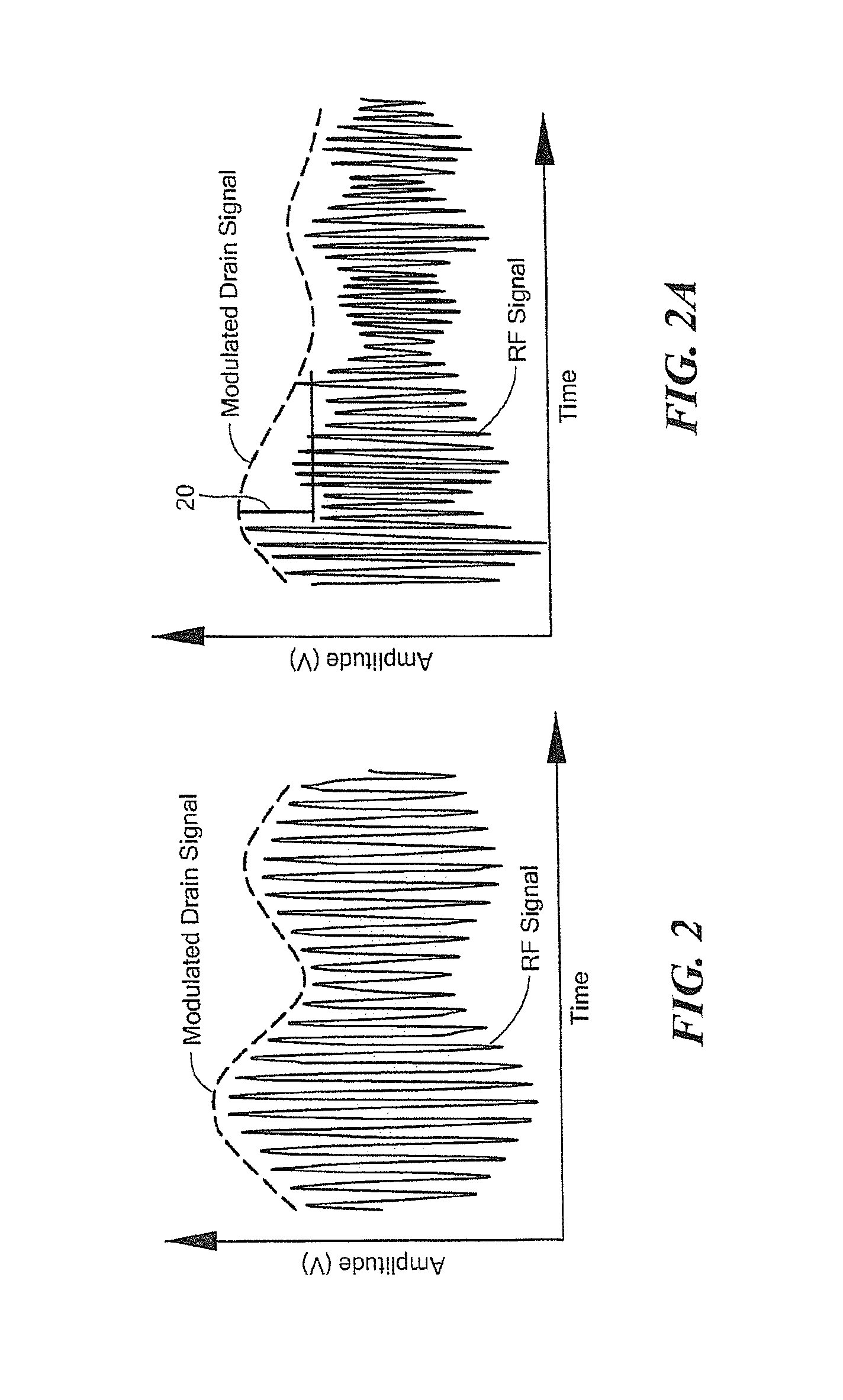
[0045]Referring now to FIGS. 2 and 2A, FIG. 2 is a plot of RF signal voltage and drain modulation voltage vs. time which illustrates traditional envelope tracking while FIG. 2A is a plot of RF signal voltage and drain modulation voltage vs. time which illustrates the bandwidth-optimized, drain-modulation envelope tracking technique described herein.

[0046]As can be seen from FIG. 2, a drain modulated voltage signal (dashed line in FIG. 2), closely follows the envelope of a modulated RF signal. Inspection of FIG...


PUM


Abstract

An apparatus and technique for operating an RF amplifier having a pre-distortion processor and a drain modulation circuit includes generating a compensating drain bias signal having a value which is a function of an RF input signal, a sampled RF output signal and a sampled drain bias signal. The compensating drain bias signal is applied to the RF amplifier. By sampling both the drain bias signal and the RF output signal and providing drain feedback and RF output feedback signals to a pre-distortion processor, RF amplifier distortions can be linearized enabling the RF amplifier to operate over a bandwidth which exceeds the bandwidth of the drain modulation circuit (i.e., the RF bandwidth can exceed the bandwidth of the drain modulator).

Description

CROSS REFERENCE TO RELATED APPLICATION[0001]This application claims the benefit of U.S. Provisional Application No. 61 / 473,945 filed Apr. 11, 2011 under 35 U.S.C. §119(e) which application is hereby incorporated herein by reference in its entirety.GOVERNMENT RIGHTS[0002]Not applicable.FIELD OF THE INVENTION[0003]The structures and techniques described herein relate to radio frequency (RF) circuits and more particularly to RF amplifier circuits.BACKGROUND OF THE INVENTION[0004]As is known in the art, in telecommunications systems, satellite systems and other systems, it is desirable for radio frequency (RF) power amplifiers (PAs) to linearly amplify RF signals in a highly efficient manner. Efficiency is generally proportional to input drive level. High efficiency is typically not attained until an amplifier approaches its maximum output power. This, however, is not consistent with linear operation. Thus, a tradeoff must typically be made between achieving maximum efficiency and high ...

Claims


Application Information

Patent Timeline
Patent Type & Authority Patents(United States)
IPC IPC(8): H03F1/26
CPCH03F1/0216H03F1/3247
Inventor ROYER, MARK A.
Owner AURIGA MEASUREMENT SYST
Why Eureka
Try Eureka