
Methods, apparatus, and systems for prediction of lighting module performance

Active Publication Date: 2013-12-17
OSRAM SYLVANIA INC
View PDF451 Cites 98 Cited by
  • Summary
  • Abstract
  • Description
  • Claims
  • Application Information

AI Technical Summary

Benefits of technology

The invention describes a method of compensating for failure in a network of LED lighting fixtures. When a failure occurs, neighboring fixtures detect it and increase their light level to maintain the desired lighting on surfaces. This is done by overdriving neighboring LED light bars. The method uses intelligent sensing to detect the presence of dead light bars and compensates for failures in an efficient and effective way.

Problems solved by technology

However, none of the systems discloses a one-size-fits-all approach to include a large number of fixtures.
In addition, the installation of such systems may be costly due to expenses incurred on wiring and power.
Also, conventional systems may rely on low-tech occupancy or ambient light sensors that may not be feasible solutions with respect to environmental conditions.
Additionally, these systems may not be equipped to include variability in electricity pricing models.

Method used


Image

  • Methods, apparatus, and systems for prediction of lighting module performance
  • Methods, apparatus, and systems for prediction of lighting module performance
  • Methods, apparatus, and systems for prediction of lighting module performance

Examples


Embodiment Construction

)

[0145]While the specification concludes with the claims defining the features of the invention that are regarded as novel, it is believed that the invention will be better understood from a consideration of the following description in conjunction with the drawings / figures, in which like reference numerals are carried forward.

[0146]As required, detailed embodiments of the present invention are disclosed herein; however, it is to be understood that the disclosed embodiments are merely exemplary of the invention, which can be embodied in various forms. Therefore, specific structural and functional details disclosed herein are not to be interpreted as limiting, but merely as a basis for the claims and as a representative basis for teaching one skilled in the art to variously employ the present invention in virtually any appropriately detailed structure. Further, the terms and phrases used herein are not intended to be limiting but rather to provide an understandable description of the...


PUM


Abstract

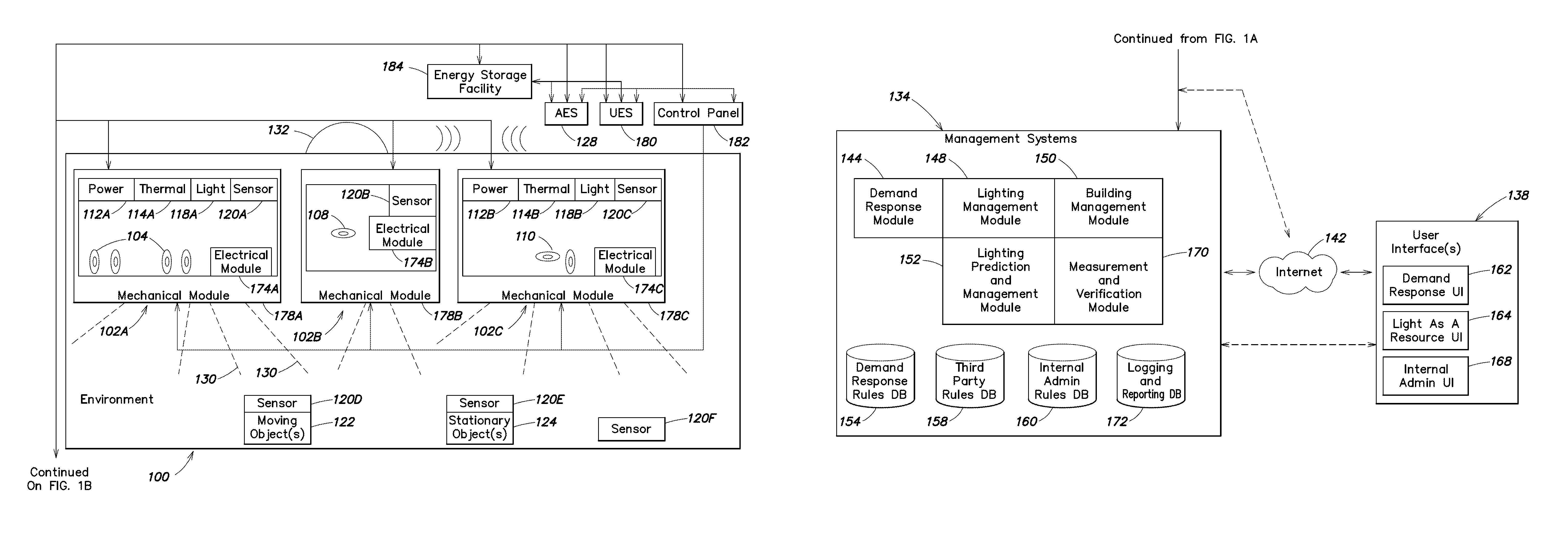
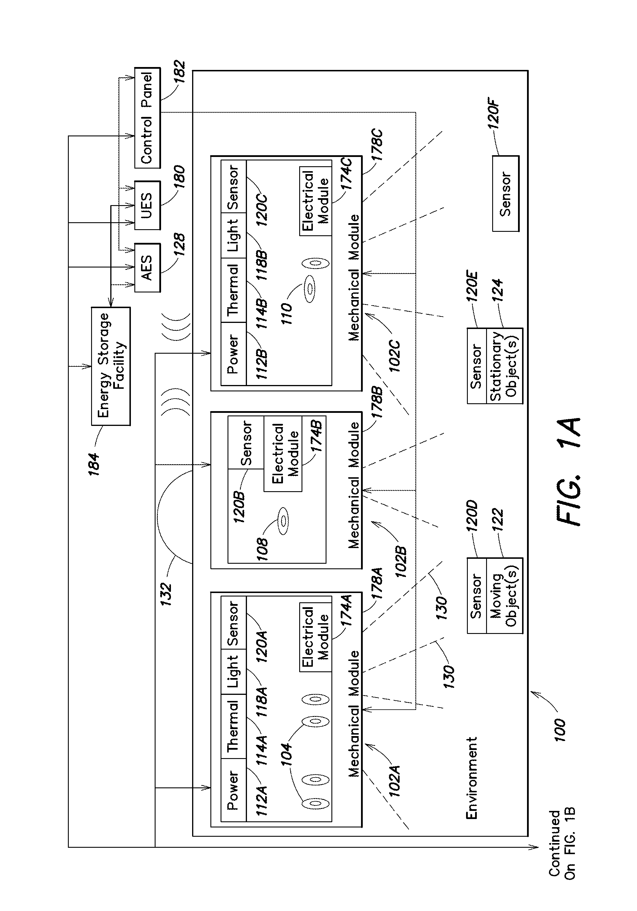
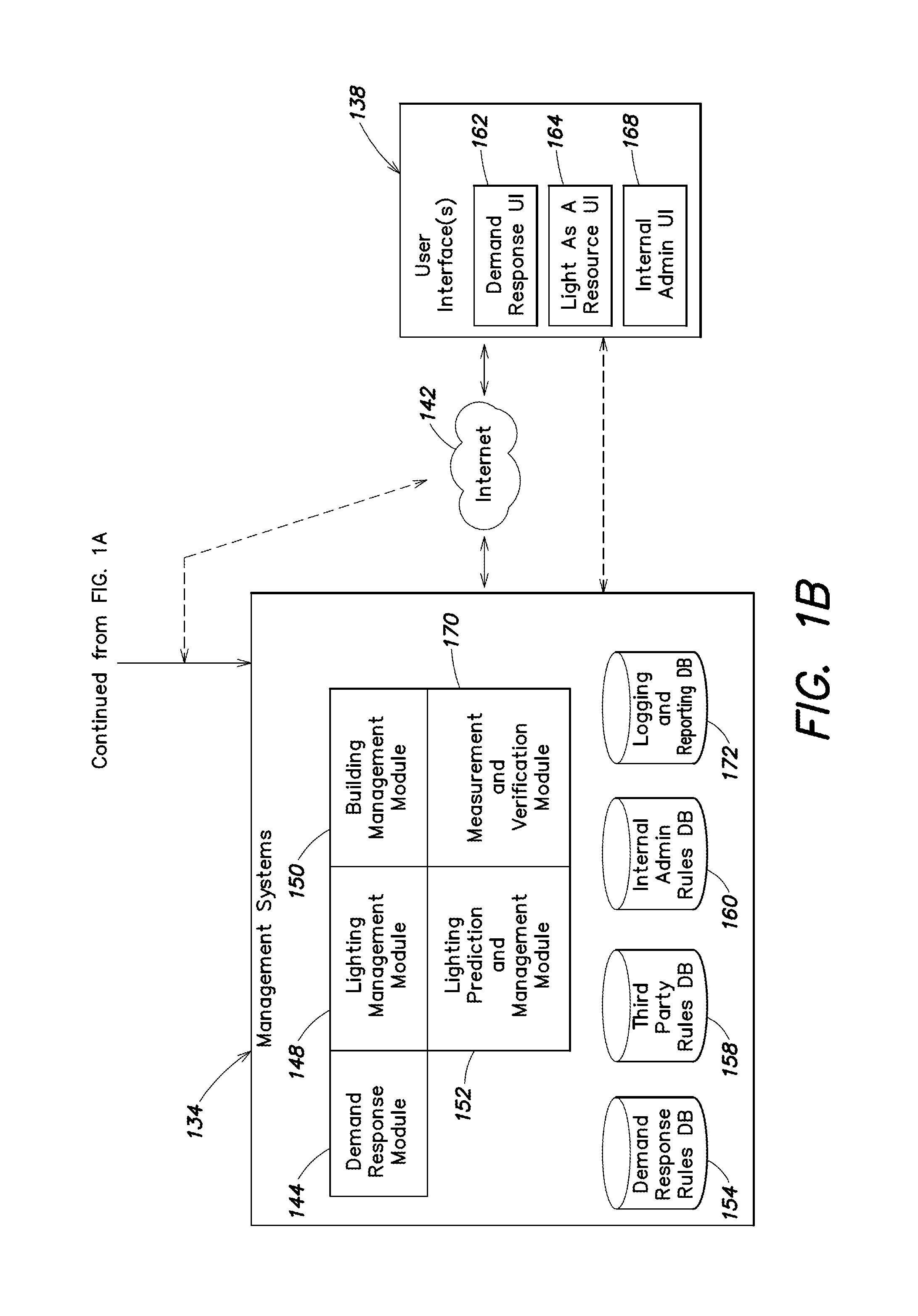
In embodiments of the present invention, a method and system is provided for designing improved intelligent, LED-based lighting systems. The LED based lighting systems may include fixtures with one or more of rotatable LED light bars, integrated sensors, onboard intelligence to receive signals from the LED light bars and control the LED light bars, and a mesh network connectivity to other fixtures.

Description

CROSS-REFERENCE TO RELATED APPLICATIONS[0001]This application claims the benefit of the following provisional applications, each of which is hereby incorporated by reference in its entirety: U.S. Provisional Application No. 61 / 303,608, filed Feb. 11, 2010; and U.S. Provisional Application No. 61 / 303,278, filed Feb. 10, 2010.[0002]This application is a continuation-in-part of the following U.S. patent applications, each of which is incorporated by reference in its entirety: U.S. patent application Ser. No. 12 / 423,543, filed Apr. 14, 2009 now U.S. Pat. No. 8,232,745 and U.S. patent application Ser. No. 12 / 423,361 also filed Apr. 14, 2009 now abandoned. Each of the foregoing U.S. patent applications claim the benefit of the following provisional applications, each of which is hereby incorporated by reference in its entirety: U.S. Provisional Application No. 61 / 044,591, filed Apr. 14, 2008; U.S. Provisional Application No. 61 / 055,727, filed May 23, 2008; U.S. Provisional Application No....

Claims


Application Information

Patent Timeline
IPC IPC(8): G05F1/00
CPCH05B37/029Y02B20/48H05B47/155Y02B20/40
Inventor CHEMEL, BRIAN J.PIEPGRAS, COLINKONDO, STEVE T.JOHNSTON, SCOTT D.
Owner OSRAM SYLVANIA INC
Learn More