Rotary table device which can be tuned flexibly to operate individually

Inactive Publication Date: 2013-12-17
HUNG KUN JUNG
View PDF4 Cites 1 Cited by
  • Summary
  • Abstract
  • Description
  • Claims
  • Application Information

AI Technical Summary

Benefits of technology

The present invention is a rotary table device that can operate simultaneously and individually. It consists of a main frame, a round outer seal plate, a round inner seal plate, at least two driving wheels and at least two driven wheels. Each driving wheel is connected with a sliding block, and an adapter plate is combined with a die (mount) fixing plate, which is placed on the sliding block. Each driving wheel can rotate independently in the track region and displace at a fixed site to perform all manufacturing processes. The device is flexible to operate individually and can support a few dies (mounts) simultaneously. The technical effect of this invention is to provide a flexible and efficient tool for manufacturing processes.

Problems solved by technology

The existing rotary table device is provided with several shortcomings:1. There are a lot of dies (mounts), which increases the cost,2. The labor time and fees for repairing and die changing will be increased.3. There is a higher probability to result in a larger tolerance when processing, installing and tuning plural dies (mounts) and therefore, the product stability will be reduced, correspondingly.4. It is unable to flexibly tune the operation time of each fixed-site manufacturing process.5. When a manufacturing process needs to be displaced immediately after accomplishing in a short machine-hour to proceed with the next manufacturing process, the manufacturing process that spends the longest time must be accomplished before all the rotary tables displace together to the next manufacturing process.
Therefore, the prime time is missed and the percent defective will be increased.6. It is relatively more difficult for the manufacturing process to increase the fixed sites.

Method used


Image

  • Rotary table device which can be tuned flexibly to operate individually
  • Rotary table device which can be tuned flexibly to operate individually
  • Rotary table device which can be tuned flexibly to operate individually

Examples


Embodiment Construction

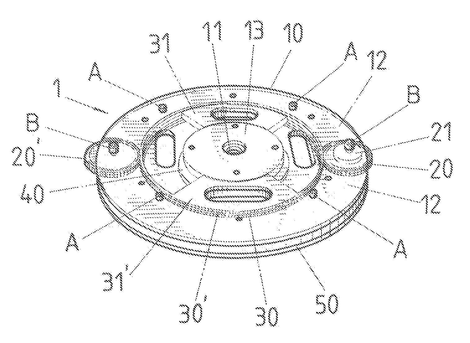
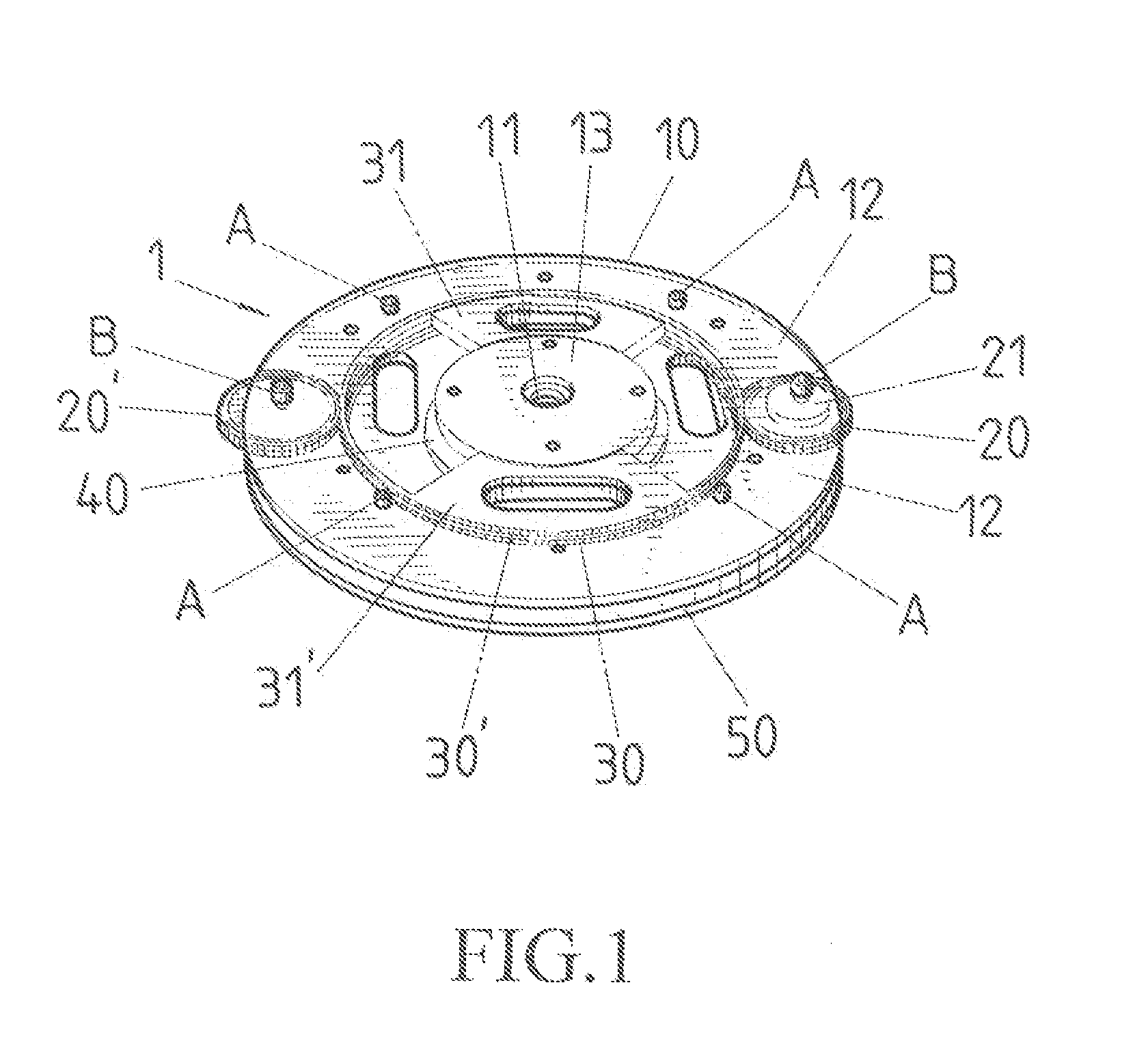
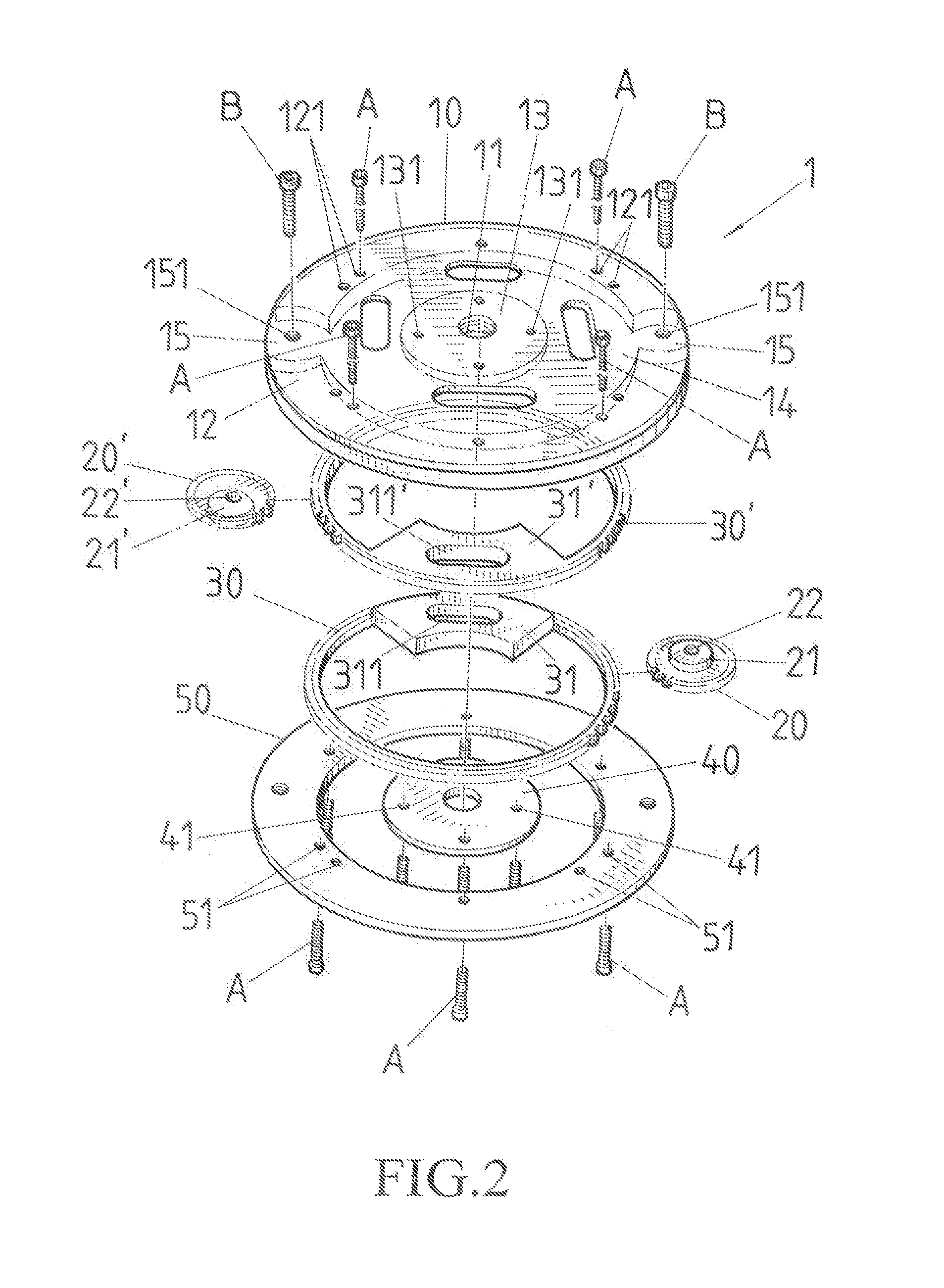
[0036]Referring to FIG. 1 and FIG. 2, a rotary table 1 of the present invention comprises:

[0037]a main frame 10, a center of which is provided with a rotary table central indexing hole 11, an interior side of which is provided with an inner annular track region 13, and an exterior side of which is provided with an outer annular track region 12, with that two driving-wheel emplacement regions 15 are provided respectively at a proper location on the outer annular track region 12, a driven-wheel annular track region 14 is provided between the inner and outer annular track regions 13, 12, each driving-wheel emplacement region 15 is provided with a driving-wheel central shaft hole 151 and plural screw holes 131, 121 are provided on the inner and outer annular track regions 13, 12;

[0038]at least two driving wheels 20, 20′ which are installed respectively in the driving-wheel emplacement region 15 of the main frame 10, with that the driving wheels 20,20′ are provided respectively with whee...


PUM


Abstract

A rotary table with a main frame, at least two driving wheels, at least two driven wheels, a round inner seal plate and a round outer seal plate. The main frame is provided with an inner and outer annular track region. Driving-wheel emplacement regions are at proper locations on the outer annular track region and driven-wheels are installed in a drive-wheel annular track region between the inner and outer annular track regions. The driving wheels are installed in the driving-wheel emplacement regions of the main frame. A side of the drive-wheel is connected with a sliding block. The driven wheel is matched and gnawed with the driving wheel which can drive individually the matched and gnawed driven wheel to rotate and displace to perform plural manufacturing processes of a short machine-hour and plural fixed sites, such that all the manufacturing processes can be accomplished simultaneously.

Description

BACKGROUND OF THE INVENTION[0001]a) Field of the Invention[0002]The present invention relates to a rotary table device which can be tuned flexibly to operate individually, and more particularly to a rotary table, wherein manufacturing processes of plural fixed sites, a long machine-hour and a short machine-hour can be tuned flexibly to operate individually by a few dies (mounts), so that the operation time, the cost of dies (mounts) and the die-change time can be reduced, thereby decreasing the percent defective and increasing the capacity.[0003]b) Description of the Prior Art[0004]It is known that when ordinary rotary tables are operating, there must be an equal amount of dies (mounts) to the number of fixed-site manufacturing processes and the rotary tables can rotate together only after accomplishing the manufacturing process that spends the longest time to proceed with the next manufacturing process. The existing rotary table device is provided with several shortcomings:[0005]1....

Claims


Application Information

Patent Timeline
IPC IPC(8): F16H48/12
CPCE21B3/04Y10T74/19005
Inventor HUNG, KUN-JUNG
Owner HUNG KUN JUNG
Why Eureka
Try Eureka